
ProLiant DL360 G4 and G4p Server High Density Deployment Solution White Paper


30
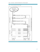
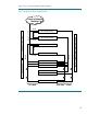
Figure 14 is a conventional Ethernet cable diagram.
Figure 14.Configuration C (Conventional) Ethernet Cable
48 Port Switch (44 FE + 4 GbE) 1
48 Port Switch (44 FE + 4 GbE) 2
Server 01
Server 02
Server 03
Server 28
8x GbE + 4x FE
4x GbE
Servers in Rack
NIC 1 (GbE) NIC 2 (GbE)
28 x FE
28 x FE
6 x FE
Switches on top of Rack
Server 14
Server 15
24 Port Hub (24 FE) 2
24 Port Hub (24 FE) 1
iLO (FE)
14 x FE
14 x FE
2x FE
2x FE
6 x FE
Uplink to Network
Backbone
84 x Cat 5 Cables Routed Inside Server Cabinet