
HP ProLiant DL360 Generation 4p Server Maintenance and Service Guide

Removal and replacement procedures 24
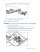
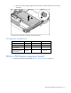
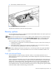
SATA backplane
1. Power down the server (on page 12).
2. Remove all SATA hard drives ("Hard drive" on page 16).
3. Eject the optical device ("Optical device" on page 18).
4. Extend or remove the server from the rack ("Extending the server from the rack" on page 12).
5. Remove the access panel ("Access panel" on page 14).
6. Remove the optical device and diskette drive interface ("Optical device and diskette drive interface"
on page 22).
7. Disconnect all cables connected to the SATA backplane. For cable locations, refer to the SATA cable
routing (on page 37) information.
8. Remove the component from the server.
To replace the component, reverse the removal procedure.
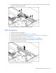
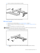
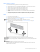
PCI riser board assembly
CAUTION: To prevent damage to the server or expansion boards, power down the server and remove all
AC power cords before removing or installing the expansion boards.
IMPORTANT: Be sure that all DIMM slot latches are closed to provide adequate clearance before
removing the PCI riser board assembly with a half-length expansion board.
1. Power down the server (on page 12).
2. Extend the server from the rack, if applicable ("Extending the server from the rack" on page 12).
3. Remove the access panel ("Access panel" on page 14).
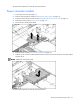
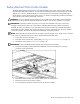
4. Remove the PCI riser board assembly:
a. Disconnect any internal or external cables connected to any existing expansion boards.
b. Loosen the four PCI riser board assembly thumbscrews.