
ProLiant Server High-Density Deployment Server Solution


Configuration A: Maximum Performance Density
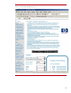
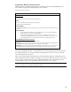
Table 7 describes a suggested configuration for a 42U rack with 42 ProLiant DL360 G4 servers
powered from a single or dual high-voltage AC power supplies.
Table 7. Configuration A Summary
Configuration A Summary
Rack Contents
Rack
HP ProLiant Model 10462 rack with 42U of mounting space
Units
42 Servers with all fixed or all sliding rails with cable trays
4 High-voltage 40-A Modular PDUs
Internal Cables
42 Standard IEC-TO-IEC jumper cords going to the servers from the extension bars mounted at the rear
of the rack
External Cables
• 42 management network cables from the iLO RJ-45 connector to external 48 port Ethernet
switches with 44 10/100 ports and 4 Gigabit ports
• 84 data network cables from the on-board 10/100/1000 NICs RJ-45 connectors to 6
external 24-port Gigabit Ethernet switches, assuming use of two LAN connections per server
• 2 high-voltage input power cords hardwired from the PDUs to facility AC power feeds
Site Utility Requirements (worst-case)
Power: 2 dedicated 200 V - 240 V 50-A branch circuits.
Thermal: Up to 80,000 BTUs/hour (This number is a worst-case. The actual BTUs/hour will depend on
the OS/application software running and the server hardware configurations.)
Weight: Up to 907.18 kg (2,000 lb) (with sliding-rails) (The network cables are not accounted for since
most implementations route the network cables to the ceiling-hung cable rails outside of the rack.)
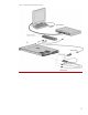
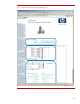
The optional iLO Advanced Pack is recommended for all console management (local and remote) for
this configuration (Figure 9). The network cables originating from each server connect to network
switches outside this rack enclosure.
The use of the double-bar mounting brackets for the Modular PDU is highly recommended. This will
allow the maximum number of outlets to mounted on the same side of the rack enclosure as the server
power supply connection. The fixed length cord PDU significantly reduces cable bulk from power
cords. The PDU is 20 cm (8 in) long, and the cables are each 33 cm (13 in) long.
Note: No KVM switches are used in Configuration A. The iLO Advanced Pack handles all the local
consoles. See Figure 9 for the Ethernet Cable Diagram.
20