
ProLiant DL360 G2 Server High-Density Deployment

ProLiant DL360 G2 Server High-Density Deployment 36
Repeat the procedure for any subsequent rack rails. For detailed instructions on installing
standard rack rails, refer to the Compaq ProLiant DL360 G2 Server Setup and Installation Guide
and to the Compaq ProLiant DL360 G2 Hardware Configuration and Installation Poster.
CAUTION: Always install servers from the bottom of the rack to the top. Installing
servers in this manner provides more stability for the rack and reduces the risk of the rack
tipping over.
IMPORTANT: Before installing the rack rails for the standard rack rails and cable
management arm, remove the server rails from the slide rail assembly. See the “Server
Preparation” section in this document for more information.
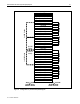
IMPORTANT: Install a ProLiant DL360 G2 server in every U-space from the bottom to the
top for maximum density.
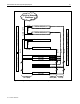
Installing a Server in a Rack
Install ProLiant DL360 G2 servers in the rack from the bottom to the top. Tighten the
thumbscrews on the front of each server to secure the server to the rack. Attach the cable
management arm to the rear of the server and to the rear of the rack.
WARNING: To reduce the risk of serious personal injury, fire, or damage to the
equipment:
• Extend the leveling jacks to the floor and rest the full weight of the rack on the
leveling jacks.
• Install either the stabilizer kit or couple multiple racks together for stability.
• Load the heaviest item first and load the rack from the bottom to the top. Loading the
rack in this manner makes the rack “bottom-heavy” and helps prevent the rack from
becoming unstable.
• Do not overload the AC supply branch circuit that provides power to the rack.
• Extend only one ProLiant DL360 G2 server at a time. A rack might become unstable
if more than one server is fully extended for any reason.
Connecting Cables
This section discusses connecting and routing cables with different cable management solutions
and different console management solutions.
1. Connect the cables to each device installed in the rack, working from the bottom to the top.
2. Connect the cables to the bottom piece of equipment.
3. Bundle the cables and route them through the cable management solution.
4. Connect the cables to the console switchbox.
5. Connect the power cord to the PDU. Do not connect the PDU to any power source until all
equipment is fully deployed in the rack.
1713-0702A-WWEN