
ProLiant DL320 Setup and Installation Guide

Installing Hardware Options 3-47
Compaq Confidential – Need to Know Required
Writer: Gilbert Saldivar Project: Compaq ProLiant DL320 Setup and Installation Guide Comments:
Part Number: 203836-001 File Name: d-ch3 Installing Hardware Options.doc Last Saved On: 8/23/00 4:00 PM
Installing a Compaq Smart Array
Controller in a System with ATA Drives
Compaq offers a two-device SCSI cable as an option for installing SCSI hard
drives and a Compaq Smart Array controller into a ProLiant DL320 server
with ATA hard drives. To perform this installation, refer to the documentation
that shipped with your option kit.
CAUTION: When supporting a mixed environment of ATA drives and SCSI drives
in a ProLiant DL320 server, the ATA drive must be the boot device.
NOTE: When using the Smart Array controller to manage internal drives, you must
remove the ATA module.
NOTE: Refer to the documentation that ships with your Smart Array controller for
restrictions on using both internal and external SCSI connectors.
NOTE: You can run ATA drives internally while running external SCSI drives.
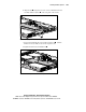
Use the following procedures to install two internal SCSI hard drives with
RAID management into a ProLiant DL320 server with ATA hard drives:
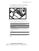
1. Review the “Guidelines for Installing Hard Drives” earlier in this
chapter to ensure proper jumper settings and hard drive configuration.
NOTE: Steps 2 through 4 apply only to servers that have already been mounted in a rack.
2. Back up the data residing on any ATA hard drives in your server.
3. Power down the server. See “Powering Down the Server” earlier in this
chapter.
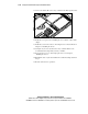
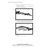
4. Remove the server from the rack. See “Removing the Server from the
Rack” in Chapter 4, “Installing the Server.”
NOTE: If you install the rack management solution option (ball-bearing slide rails and a
cable management system), you can perform many hardware procedures without
removing the server from the rack. For more information, see “Other Options” earlier in
this chapter.
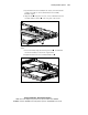
5. Remove the access panel. See “Removing the Access Panel” earlier in
this chapter.
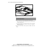
6. Remove the PCI riser board assembly. See “Removing the PCI Riser
Board Assembly” earlier in this chapter.