HP ProLiant DL320 Generation 5p Server User Guide Part Number 451883-003 October 2008 (Third Edition)
© Copyright 2007, 2008 Hewlett-Packard Development Company, L.P. The information contained herein is subject to change without notice. The only warranties for HP products and services are set forth in the express warranty statements accompanying such products and services. Nothing herein should be construed as constituting an additional warranty. HP shall not be liable for technical or editorial errors or omissions contained herein. Microsoft, Windows, and Windows NT are U.S.
Contents Component identification ............................................................................................................... 7 Front panel components ............................................................................................................................. 7 Front panel components (standard configuration)................................................................................. 7 Front panel components (optional hard drive cage configuration) .................
Introduction ............................................................................................................................................ 30 Memory options ...................................................................................................................................... 30 Interleaving and non-interleaving memory configuration ..................................................................... 30 DIMM installation guidelines .............................................
Array Diagnostic Utility .................................................................................................................. 63 Manual ROMPaq disaster recovery.................................................................................................. 63 Keeping the system current ....................................................................................................................... 63 Drivers ..............................................................................
Specifications ............................................................................................................................. 91 Environmental specifications ..................................................................................................................... 91 Server specifications ................................................................................................................................ 91 Technical support..............................................
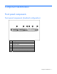
Component identification Front panel components Front panel components (standard configuration) Item Description 1 Hard drive bay 1 2 Hard drive bay 2 3 Serial label pull tab 4 12.
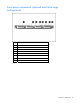
Front panel components (optional hard drive cage configuration) Item Description 1 Hard drive bay 1 2 Hard drive bay 2 3 9.
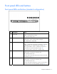
Front panel LEDs and buttons Front panel LEDs and buttons (standard configuration) Item Description Status 1 12.7-mm optical drive activity LED Green = Drive activity is normal. Amber = Drive failure has occurred. Off = No drive activity exists. 2 UID button/LED Blue = Identification is activated. Flashing blue = System is being remotely managed. Off = Identification is deactivated. 3 Internal health LED Green = System health is normal. Amber = System health is degraded.
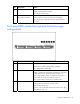
Item Description Status 6 Drive activity LED Green = Drive activity is normal. Amber = Drive failure has occurred. Off = No drive activity exists. 7 Power On/Standby button and system power LED Green = System is on. Amber = System is shut down, but power is still applied. Off = Power cord is not attached or power supply failure has occurred. Front panel LEDs and buttons (optional hard drive cage configuration) Item Description Status 1 UID button/LED Blue = Identification is activated.
Item Description Status 4 NIC 2 link/activity LED Green = Network link exists. Flashing green = Network link and activity exist. Off = No network link exists. If power is off, the front panel LED is not active. View the LEDs on the RJ-45 connector. See "Rear panel LEDs (on page 13)." 5 Drive activity LED Green = Drive activity is normal. Amber = Drive failure has occurred. Off = No drive activity exists. 6 Power On/Standby button and system power LED Green = System is on.
SATA device numbers (optional hard drive cage configuration) Rear panel components For this server model, PCI expansion slots 1-3 and 6-7 are reserved.
Item Description 8 UID button/LED 9 Video connector 10 Dedicated iLO 2 management port (optional) 11 10/100/1000 NIC 1/shared iLO 2 management port 12 Keyboard connector PCI expansion slot definitions For this server model, PCI expansion slots 1-3 and 6-7 are reserved. Slot Type Length Connector Interconnect 4 PCI Express Full x8 x8 4 Optional PCI-X Full 133 MHz/3.3. V 64 bit 5 PCI Express* Half x8 x1 *x8 PCI Express cards are supported, but will run at x1 speeds.
System board components For this server, some system board slots and connectors are reserved.
Item Description 23 Reserved 24 SATA connector 5 (optical drive)* 25 Internal USB option connector 26 Reserved 27 SATA connector 3 (hard drive) 28 SATA connector 1 (hard drive) 29 Parallel option connector 30 Serial option connector 31 Reserved 32 PCI Express expansion slot 4 33 PCI Express expansion slot 5** 34 Reserved 35 Reserved 36 Reserved 37 Dedicated iLO2 optional module connector * The server supports one optical drive that can be connected to either SATA connector 5
NMI functionality An NMI crash dump enables administrators to create crash dump files when a system is hung and not responding to traditional debug mechanisms. Crash dump log analysis is an essential part of diagnosing reliability problems, such as hangs in operating systems, device drivers, and applications. Many crashes freeze a system, and the only available action for administrators is to cycle the system power.
Item LED description Status 4 Fan 2 failure Amber = Fan 2 has failed or is missing. Off = Normal 5 Fan 3 failure Amber = Fan 3 has failed or is missing. Off = Normal 6 PCI fan failure Amber = PCI fan has failed or is missing. Off = Normal 7 Overtemperature Amber = System has reached a cautionary or critical temperature level. 8 DIMM 4 failure Amber = DIMM has failed or is missing. Off = Normal 9 DIMM 3 failure Amber = DIMM has failed or is missing.
System LED and Color Internal Health LED Color Status Amber • DIMM in slot X has reached single-bit correctable error threshold. • DIMM in slot X is in a pre-failure condition. • DIMM in slot X is an unsupported type, but valid memory exists in another bank. DIMM failure, all slots in one bank (amber) Red No valid or usable memory is installed in the system. Overtemperature (amber) Amber The Health Driver has detected a cautionary temperature level.
Fan locations Standard configurations include either three or four fans.
Operations Power up the server To power up the server, press the Power On/Standby button. Power down the server WARNING: To reduce the risk of personal injury, electric shock, or damage to the equipment, remove the power cord to remove power from the server. The front panel Power On/Standby button does not completely shut off system power. Portions of the power supply and some internal circuitry remain active until AC power is removed.
4. Remove the server from the rack. For more information, see the documentation that ships with the rack mounting option. 5. Place the server on a sturdy, level surface. Remove the primary access panel WARNING: To reduce the risk of personal injury from hot surfaces, allow the drives and the internal system components to cool before touching them. CAUTION: Do not operate the server for long periods with the access panel open or removed.
1. Power down the server (on page 20). 2. Remove the server from the rack (on page 20). 3. Remove the primary access panel (on page 21). 4. Disconnect any internal or external cables connected to any existing expansion boards. 5. Remove the PCI riser board assembly. Install the PCI riser board assembly CAUTION: To prevent damage to the server or expansion boards, power down the server and remove all AC power cords before removing or installing the PCI riser board assembly. 1.
4. Install the server into the rack.
Setup Optional installation services Delivered by experienced, certified engineers, HP Care Pack services help you keep your servers up and running with support packages tailored specifically for HP ProLiant systems. HP Care Packs let you integrate both hardware and software support into a single package. A number of service level options are available to meet your needs.
• Leave a minimum clearance of 63.5 cm (25 in) in front of the rack. • Leave a minimum clearance of 76.2 cm (30 in) behind the rack. • Leave a minimum clearance of 121.9 cm (48 in) from the back of the rack to the back of another rack or row of racks. HP servers draw in cool air through the front door and expel warm air through the rear door.
Power requirements Installation of this equipment must comply with local and regional electrical regulations governing the installation of information technology equipment by licensed electricians. This equipment is designed to operate in installations covered by NFPA 70, 1999 Edition (National Electric Code) and NFPA-75, 1992 (code for Protection of Electronic Computer/Data Processing Equipment).
WARNING: To reduce the risk of personal injury or damage to the equipment, be sure that: • The leveling jacks are extended to the floor. • The full weight of the rack rests on the leveling jacks. • The stabilizing feet are attached to the rack if it is a single-rack installation. • The racks are coupled together in multiple-rack installations. • Only one component is extended at a time. A rack may become unstable if more than one component is extended for any reason.
If you are installing the server into a telco rack, order the appropriate option kit at the RackSolutions.com website (http://www.racksolutions.com/hp). Follow the server-specific instructions on the website to install the rack brackets. Use the following information when connecting peripheral cables and power cords to the server. WARNING: To reduce the risk of electric shock, fire, or damage to the equipment, do not plug telephone or telecommunications connectors into RJ-45 connectors.
To power up the server, press the Power On/Standby button. While the server boots, RBSU and the ORCA utility are automatically configured to prepare the server for OS installation. • Press the F8 key when prompted during the array controller initialization to configure the array controller using ORCA. The array controller defaults to RAID 0 with one drive installed and RAID 1 with more than one drive installed.
Hardware options installation Introduction If more than one option is being installed, read the installation instructions for all the hardware options and identify similar steps to streamline the installation process. WARNING: To reduce the risk of personal injury from hot surfaces, allow the drives and the internal system components to cool before touching them. CAUTION: To prevent damage to electrical components, properly ground the server before beginning any installation procedure.
The following table lists some, but not all, possible configurations. For best performance, HP recommends dual-bank interleaved mode configurations. Slot 1A Slot 2B Slot 3A Slot 4B Total memory Mode 512 MB — — — 512 MB Single-bank 512 MB — 512 MB — 1 GB Single-bank interleaved 1 GB — — — 1 GB Single-bank 1 GB — 1 GB — 2 GB Single-bank interleaved 1 GB 1 GB 1 GB 1 GB 4 GB Dual-bank interleaved 2 GB 2 GB 2 GB 2 GB 8 GB Dual-bank interleaved Installing DIMMs 1.
Hard drive guidelines When adding hard drives to the server, observe the following general guidelines: • The system automatically sets all drive numbers. • If only one hard drive is used, install it in the bay with the lowest drive number. • Drives must be the same capacity to provide the greatest storage space efficiency when drives are grouped together into the same drive array. Optional storage controllers provide support for hot-plug capability and drive LEDs.
CAUTION: To prevent improper cooling and thermal damage, do not operate the server unless all bays are populated with either a component or a blank. 3. Remove the hard drive. Installing a hard drive IMPORTANT: Hot-plug capability and drive LED support are only available when a supported optional controller is installed in the server. 1. Power down the server (on page 20). 2. Remove the existing hard drive blank ("Removing a hard drive blank" on page 32). 3. Prepare the hard drive.
4. Install the hard drive. Installing a four-bay hard drive cage To install the component: 1. Power down the server (on page 20). 2. Remove the server from the rack (on page 20). 3. Remove the primary access panel (on page 21). 4. Remove the secondary access panel (on page 21). 5. Disconnect the front panel LED cable and the front USB cable. 6. Disconnect the hard drive cables from the system board. 7. Disconnect cables from any other devices installed in the hard drive cage, if necessary.
9. Remove the two-bay hard drive cage. In the following illustration, the hard drive backplanes have been removed for clarity. 10. Install the four-bay hard drive cage. In the following illustration, the hard drive backplanes have been removed for clarity.
11. Route and connect the hard drive cables to the backplanes and to the system board. 12. Connect the power cables to the backplanes. 13. Connect the front panel LED cable and the front USB cable to the system board. 14. Install the secondary access panel. 15. Install the primary access panel. 16. Install the server into the rack. Optical drive assembly (12.7 mm) option To install a 12.7-mm optical drive, a server model with the two-bay hard drive cage is required. To install the component: 1.
5. Using a T-15 Torx screwdriver, remove the 12.7-mm optical drive carrier. 6. Remove the 12.7-mm optical drive blank.
7. Remove the four M2 screws required to install the 12.7-mm optical drive. 8. Install the 12.7-mm optical drive in the optical drive carrier.
9. Using a T-15 Torx screwdriver, install the interposer board. 10. Install the 12.7-mm optical drive assembly and carrier.
11. Connect the power cable and the optical drive cable to the 12.7-mm optical drive. 12. Route and connect the optical drive cable to the system board. 13. Install the secondary access panel. 14. Install the primary access panel. 15. Install the server into the rack. Optical drive assembly (9.5 mm) option To install a 9.5-mm optical drive, the optional four-bay hard drive cage is required. To install the component: 1. Power down the server (on page 20). 2.
4. Remove the secondary access panel (on page 21). 5. Remove the 9.5-mm optical drive blank. Retain the blank for future use. 6. Install the 9.5-mm optical drive assembly. When fully inserted, the assembly locking latch clicks.
7. Connect the optical drive and power cable to the 9.5-mm optical drive. 8. Route the cable and connect the cable's SATA connector to the system board. 9. Connect the cable's power connector to the power supply. 10. Install the secondary access panel. 11. Install the primary access panel. 12. Install the server into the rack. Expansion board option To install the component: 1. Power down the server (on page 20). 2. Remove the server from the rack (on page 20). 3.
4. Disconnect any internal or external cables connected to any existing expansion boards. 5. Remove the PCI riser board assembly (on page 21). 6. Remove the expansion slot cover. 7. Install the expansion board. IMPORTANT: The server does not power up if the PCI riser board assembly is not seated properly. 8. Install the PCI riser board assembly (on page 22). 9. Install the primary access panel. 10. Install the server into the rack.
PCI-X riser board option To install the component: 1. Power down the server (on page 20). 2. Remove the server from the rack (on page 20). 3. Remove the primary access panel (on page 21). 4. Disconnect any internal cables connected to any existing expansion boards. 5. Remove the PCI riser board assembly (on page 21). 6. Remove any installed expansion boards. 7. Remove the PCIe riser board from the assembly.
8. Install the optional PCI-X riser board. 9. Install the expansion board ("Expansion board option" on page 42). IMPORTANT: The server does not power up if the PCI riser board assembly is not seated properly. 10. Install the PCI riser board assembly (on page 22). 11. Connect any internal cables for expansion boards. 12. Install the primary access panel. 13. Install the server into the rack.
9. Connect the hot-plug SAS/SATA cable to the controller. For connector locations, see the documentation that ships with the controller. 10. Install the primary access panel. 11. Install the server into the rack. Battery-backed write cache battery option CAUTION: To prevent a server malfunction or damage to the equipment, do not add or remove the battery pack while an array capacity expansion, RAID level migration, or stripe size migration is in progress.
5. Install the battery. 6. Route the cable ("Battery cabling for BBWC" on page 54). 7. Connect the cable to the controller. For clarity, the server is not shown in this illustration. Dedicated iLO2 optional module connector To install the component: 1. Power down the server (on page 20). 2. Remove the server from the rack (on page 20). 3. Remove the primary access panel (on page 21).
4. Remove the management port option cover. 5. Using a T-15 Torx screwdriver, install the dedicated iLO 2 management port module. 6. Install the primary access panel. 7. Install the server into the rack. Internal USB connector option To install the component: 1. Power down the server (on page 20). 2. Remove the server from the rack (on page 20). 3. Remove the primary access panel (on page 21).
4. Using a T-15 Torx screwdriver, install the internal USB connector. 5. Route and connect the internal USB cable to the system board. 6. Install the primary access panel. 7. Install the server into the rack. SAS/SATA controller cable Depending on the model purchased, the server may look different than shown. 1. Power down the server (on page 20). 2. Remove the server from the rack (on page 20). 3. Remove the primary access panel (on page 21). 4.
6. Connect the SAS/SATA controller cable. 7. Coil cables behind the hard drive backplane to minimize airflow impact. 8. Install the secondary access panel. 9. Install the primary access panel. 10. Install the server into the rack. 11. Power up the server (on page 20). For more information on routing and connecting the cables, see "Optional SAS controller cabling (on page 52).
Cabling Cabling overview This section provides guidelines that help you make informed decisions about cabling the server and hardware options to optimize performance. Server cabling CAUTION: When routing cables, always be sure that the cables are not in a position where they can be pinched or air flow can be blocked. IMPORTANT: Route the cables without blocking the airflow or other installed components. Use the cable clips installed in the chassis to manage cable routing.
Embedded SATA controller cabling (optional hard drive cage configuration) CAUTION: When routing cables, always be sure that the cables are not in a position where they can be pinched or air flow can be blocked. Optional SAS controller cabling Optional SAS controller cabling (standard configuration) CAUTION: When routing cables, always be sure that the cables are not in a position where they can be pinched or air flow can be blocked.
Optional SAS controller cabling (optional hard drive cage configuration) CAUTION: When routing cables, always be sure that the cables are not in a position where they can be pinched or air flow can be blocked.
Battery cabling for BBWC BBWC battery cabling to an optional controller in slot 4 BBWC battery cabling to an optional controller in slot 5 Cabling 54
Optional internal USB cabling Cabling 55
Configuration and utilities Configuration tools SmartStart software SmartStart is a collection of software that optimizes single-server setup, providing a simple and consistent way to deploy server configuration. SmartStart has been tested on many ProLiant server products, resulting in proven, reliable configurations.
HP ROM-Based Setup Utility RBSU is a configuration utility embedded in ProLiant servers that performs a wide range of configuration activities that can include the following: • Configuring system devices and installed options • Enabling and disabling system features • Displaying system information • Selecting the primary boot controller • Configuring memory options • Language selection For more information on RBSU, see the HP ROM-Based Setup Utility User Guide on the Documentation CD or the HP
NOTE: If the boot drive is not empty or has been written to in the past, ORCA does not automatically configure the array. You must run ORCA to configure the array settings. Drives installed Drives used RAID level 1 1 RAID 0 2 2 RAID 1 3, 4, 5, or 6 3, 4, 5, or 6 RAID 5 More than 6 0 None To change any ORCA default settings and override the auto-configuration process, press the F8 key when prompted. By default, the auto-configuration process configures the system for the English language.
• Remains available any time that the server is on • Displays on-screen tips for individual steps of a configuration procedure For optimum performance, the minimum display settings are 800 × 600 resolution and 256 colors. Servers running Microsoft® operating systems require Internet Explorer 5.5 (with Service Pack 1) or later. For Linux servers, refer to the README.TXT file for additional browser and support information.
functioning properly, the system periodically resets the timer. However, when the operating system fails, the timer expires and restarts the server. ASR increases server availability by restarting the server within a specified time after a system hang or shutdown. At the same time, the HP SIM console notifies you by sending a message to a designated pager number that ASR has restarted the system. You can disable ASR from the HP SIM console or through RBSU.
HP Systems Insight Manager HP SIM is a web-based application that allows system administrators to accomplish normal administrative tasks from any remote location, using a web browser. HP SIM provides device management capabilities that consolidate and integrate management data from HP and third-party devices. IMPORTANT: You must install and use HP SIM to benefit from the Pre-Failure Warranty for processors, SAS and SATA hard drives, and memory modules.
front external USB connectors is not supported. This solution provides for use of a permanent boot drive from a USB drive key installed in the front internal connector, avoiding issues of clearance on the front of the rack and physical access to secure data. For additional security, you can individually disable the front, rear, and internal USB connectors through RBSU. Disabling the rear USB connectors in RBSU disables both rear USB ports.
o For NetWare: IML Viewer o For Windows®: IML Viewer o For Linux: IML Viewer Application • From within the iLO 2 user interface • From within HP Insight Diagnostics (on page 62) For more information, refer to the Management CD in the HP ProLiant Essentials Foundation Pack. Array Diagnostic Utility The HP Array Diagnostics Utility is a web-based application that creates a report of all HP storage controllers and disk drives.
NOTE: If you are installing drivers from the SmartStart CD or the Software Maintenance CD, refer to the SmartStart website (http://www.hp.com/servers/smartstart) to be sure that you are using the latest version of SmartStart. For more information, refer to the documentation provided with the SmartStart CD. If you do not use the SmartStart CD to install an operating system, drivers for some of the new hardware are required.
• Integrates with other software maintenance, deployment, and operating system tools • Automatically checks for hardware, firmware, and operating system dependencies, and installs only the correct ROM upgrades required by each target server To download the tool and for more information, refer to the HP website (http://h18000.www1.hp.com/support/files/index.html).
Troubleshooting Troubleshooting resources The HP ProLiant Servers Troubleshooting Guide provides procedures for resolving common problems and comprehensive courses of action for fault isolation and identification, error message interpretation, issue resolution, and software maintenance on ProLiant servers and server blades. This guide includes problemspecific flowcharts to help you navigate complex troubleshooting processes. To view the guide, select a language: • English (http://www.hp.
Important safety information Before servicing this product, read the Important Safety Information document provided with the server. Symbols on equipment The following symbols may be placed on equipment to indicate the presence of potentially hazardous conditions. This symbol indicates the presence of hazardous energy circuits or electric shock hazards. Refer all servicing to qualified personnel. WARNING: To reduce the risk of injury from electric shock hazards, do not open this enclosure.
WARNING: To reduce the risk of personal injury or damage to the equipment, be sure that: • The leveling feet are extended to the floor. • The full weight of the rack rests on the leveling feet. • The stabilizing feet are attached to the rack if it is a single-rack installation. • The racks are coupled together in multiple-rack installations. • Only one component is extended at a time. A rack may become unstable if more than one component is extended for any reason.
c. Power down the server (on page 20). 5. Disconnect any peripheral devices not required for testing (any devices not necessary to power up the server). Do not disconnect the printer if you want to use it to print error messages. 6. Collect all tools and utilities, such as a Torx screwdriver, loopback adapters, ESD wrist strap, and software utilities, necessary to troubleshoot the problem. o You must have the appropriate Health Drivers and Management Agents installed on the server.
• If a fixed cable tray is available for the server, be sure the cords and cables connected to the server are routed correctly through the tray. • Be sure each device is properly seated. Avoid bending or flexing circuit boards when reseating components. • If a device has latches, be sure they are completely closed and locked. • Check any interlock or interconnect LEDs that may indicate a component is not connected properly.
General diagnosis flowchart The General diagnosis flowchart provides a generic approach to troubleshooting. If you are unsure of the problem, or if the other flowcharts do not fix the problem, use the following flowchart. Item Refer to 1 "Symptom information (on page 69)" 2 "Loose connections (on page 69)" 3 "Service notifications (on page 69)" 4 The most recent version of a particular server or option firmware is available on the HP Support website (http://www.hp.com/support).
Item Refer to 5 "General memory problems are occurring" in the HP ProLiant Servers Troubleshooting Guide located on the Documentation CD or on the HP website (http://www.hp.com/support) 6 Server maintenance and service guide, located on the Documentation CD or the HP website (http://www.hp.com/products/servers/platforms) 7 • Server maintenance and service guide, located on the Documentation CD or the HP website (http://www.hp.
Server power-on problems flowchart Symptoms: • The server does not power on. • The system power LED is off or amber.
• The external health LED is red or amber. • The internal health LED is red or amber. NOTE: For the location of server LEDs and information on their statuses, refer to the server documentation.
Troubleshooting 75
POST problems flowchart Symptoms: • Server does not complete POST NOTE: The server has completed POST when the system attempts to access the boot device.
OS boot problems flowchart Symptoms: • Server does not boot a previously installed operating system • Server does not boot SmartStart Possible causes: • Corrupted operating system • Hard drive subsystem problem • Incorrect boot order setting in RBSU Troubleshooting 77
Item Refer to 1 HP ROM-Based Setup Utility User Guide (http://www.hp.com/servers/smartstart) 2 "POST problems flowchart (on page 76)" 3 • "Hard drive problems" in the HP ProLiant Servers Troubleshooting Guide located on the Documentation CD or on the HP website (http://www.hp.com/support) • Controller documentation 4 "HP Insight Diagnostics (on page 62)" or in the HP ProLiant Servers Troubleshooting Guide located on the Documentation CD or on the HP website (http://www.hp.
Server fault indications flowchart Symptoms: • Server boots, but a fault event is reported by Insight Management Agents (on page 61) • Server boots, but the internal health LED, external health LED, or component health LED is red or amber Troubleshooting 79
NOTE: For the location of server LEDs and information on their statuses, refer to the server documentation. Possible causes: • Improperly seated or faulty internal or external component • Unsupported component installed • Redundancy failure • System overtemperature condition Item Refer to 1 "Management agents (on page 61)" or in the HP ProLiant Servers Troubleshooting Guide located on the Documentation CD or on the HP website (http://www.hp.
POST error messages and beep codes For a complete listing of error messages, refer to the "POST error messages" in the HP ProLiant Servers Troubleshooting Guide located on the Documentation CD or on the HP website (http://www.hp.com/support). WARNING: To avoid potential problems, ALWAYS read the warnings and cautionary information in the server documentation before removing, replacing, reseating, or modifying system components.
Battery replacement If the server no longer automatically displays the correct date and time, you may need to replace the battery that provides power to the real-time clock. Under normal use, battery life is 5 to 10 years. WARNING: The computer contains an internal lithium manganese dioxide, a vanadium pentoxide, or an alkaline battery pack. A risk of fire and burns exists if the battery pack is not properly handled. To reduce the risk of personal injury: • Do not attempt to recharge the battery.
For more information about battery replacement or proper disposal, contact an authorized reseller or an authorized service provider.
Regulatory compliance notices Regulatory compliance identification numbers For the purpose of regulatory compliance certifications and identification, this product has been assigned a unique regulatory model number. The regulatory model number can be found on the product nameplate label, along with all required approval markings and information. When requesting compliance information for this product, always refer to this regulatory model number.
energy and, if not installed and used in accordance with the instructions, may cause harmful interference to radio communications. However, there is no guarantee that interference will not occur in a particular installation.
Canadian notice (Avis Canadien) Class A equipment This Class A digital apparatus meets all requirements of the Canadian Interference-Causing Equipment Regulations. Cet appareil numérique de la classe A respecte toutes les exigences du Règlement sur le matériel brouilleur du Canada. Class B equipment This Class B digital apparatus meets all requirements of the Canadian Interference-Causing Equipment Regulations.
This symbol on the product or on its packaging indicates that this product must not be disposed of with your other household waste. Instead, it is your responsibility to dispose of your waste equipment by handing it over to a designated collection point for the recycling of waste electrical and electronic equipment.
Class B equipment Laser compliance This product may be provided with an optical storage device (that is, CD or DVD drive) and/or fiber optic transceiver. Each of these devices contains a laser that is classified as a Class 1 Laser Product in accordance with US FDA regulations and the IEC 60825-1. The product does not emit hazardous laser radiation. Each laser product complies with 21 CFR 1040.10 and 1040.11 except for deviations pursuant to Laser Notice No.
Taiwan battery recycling notice The Taiwan EPA requires dry battery manufacturing or importing firms in accordance with Article 15 of the Waste Disposal Act to indicate the recovery marks on the batteries used in sales, giveaway or promotion. Contact a qualified Taiwanese recycler for proper battery disposal.
Electrostatic discharge Preventing electrostatic discharge To prevent damaging the system, be aware of the precautions you need to follow when setting up the system or handling parts. A discharge of static electricity from a finger or other conductor may damage system boards or other static-sensitive devices. This type of damage may reduce the life expectancy of the device. To prevent electrostatic damage: • Avoid hand contact by transporting and storing products in static-safe containers.
Specifications Environmental specifications Specification Value Temperature Operating1 10°C to 35°C (50°F to 90°F) Non-operating 30°C to 60°C (-22°F to 140°F) Maximum rate of temperature change Operating 10°C/hr (18°F/hr) 2,3 Non-operating 20°C/hr (36°F/hr) Relative humidity (noncondensing)*** Operating 10% to 90% Non-operating 5% to 95% Maximum wet bulb temperature (non-condensing) Operating 28°C (82.4°F) Non-operating 38.7°C (101.
Specification Value Width 44.80 cm (17.64 in) Weight (maximum configuration: all hard drives, power supplies, and processors installed) 15.20 kg (33.50 lb) Weight (minimum configuration: one hard drive, power supply, and processor installed) 11.79 kg (26.0 lb) Input requirement1 Rated line voltage 90 VAC to 264 VAC Rated input frequency 47 Hz to 63 Hz Rated input current 6.
Technical support Related documents For related documentation, refer to the Documentation CD. HP contact information For the name of the nearest HP authorized reseller: • See the Contact HP worldwide (in English) webpage (http://welcome.hp.com/country/us/en/wwcontact.html). For HP technical support: • • In the United States, for contact options see the Contact HP United States webpage (http://welcome.hp.com/country/us/en/contact_us.html).
defective part must be returned to HP. In cases where it is required to return the defective part to HP, you must ship the defective part back to HP within a defined period of time, normally five (5) business days. The defective part must be returned with the associated documentation in the provided shipping material. Failure to return the defective part may result in HP billing you for the replacement.
• Obbligatorie – Parti che devono essere necessariamente riparate dal cliente. Se il cliente ne affida la riparazione ad HP, deve sostenere le spese di spedizione e di manodopera per il servizio. • Opzionali – Parti la cui riparazione da parte del cliente è facoltativa. Si tratta comunque di componenti progettati per questo scopo. Se tuttavia il cliente ne richiede la sostituzione ad HP, potrebbe dover sostenere spese addizionali a seconda del tipo di garanzia previsto per il prodotto.
enthalten ist. Wenn Sie das defekte Teil nicht zurückschicken, kann HP Ihnen das Ersatzteil in Rechnung stellen. Im Falle von Customer Self Repair kommt HP für alle Kosten für die Lieferung und Rücksendung auf und bestimmt den Kurier-/Frachtdienst. Weitere Informationen über das HP Customer Self Repair Programm erhalten Sie von Ihrem Servicepartner vor Ort. Informationen über das CSR-Programm in Nordamerika finden Sie auf der HP Website unter (http://www.hp.com/go/selfrepair).
dat onderdeel rechtstreeks naar u, zodat u het defecte onderdeel daarmee kunt vervangen. Er zijn twee categorieën CSR-onderdelen: • Verplicht: Onderdelen waarvoor reparatie door de klant verplicht is. Als u HP verzoekt deze onderdelen voor u te vervangen, worden u voor deze service reiskosten en arbeidsloon in rekening gebracht. • Optioneel: Onderdelen waarvoor reparatie door de klant optioneel is. Ook deze onderdelen zijn ontworpen voor reparatie door de klant.
necessário, é preciso enviar a peça com defeito à HP dentro do período determinado, normalmente cinco (5) dias úteis. A peça com defeito deve ser enviada com a documentação correspondente no material de transporte fornecido. Caso não o faça, a HP poderá cobrar a reposição. Para as peças de reparo feito pelo cliente, a HP paga todas as despesas de transporte e de devolução da peça e determina a transportadora/serviço postal a ser utilizado.
Technical support 99
Technical support 100
Acronyms and abbreviations ABEND abnormal end ACU Array Configuration Utility ASR Automatic Server Recovery BIOS Basic Input/Output System DDR double data rate IEC International Electrotechnical Commission iLO Integrated Lights-Out IML Integrated Management Log KVM keyboard, video, and mouse LED light-emitting diode NEMA National Electrical Manufacturers Association NFPA National Fire Protection Association Acronyms and abbreviations 101
NIC network interface controller NMI non-maskable interrupt NVRAM non-volatile memory ORCA Option ROM Configuration for Arrays PCI peripheral component interface PCI Express Peripheral Component Interconnect Express PCI-X peripheral component interconnect extended PDU power distribution unit POST Power-On Self Test PPM processor power module PSP ProLiant Support Pack RAID redundant array of inexpensive (or independent) disks RBSU ROM-Based Setup Utility RDP Rapid Deployment Pack Acronyms and a
ROM read-only memory SAS serial attached SCSI SATA serial ATA SCSI small computer system interface SDRAM synchronous dynamic RAM SIM Systems Insight Manager TMRA recommended ambient operating temperature UID unit identification USB universal serial bus VCA Version Control Agent VCRM Version Control Repository Manager Acronyms and abbreviations 103
Index 1 12.7-mm optical drive 36 9 9.
F J fan LED 16 fans 19 features 7 Federal Communications Commission (FCC) notice 84, 85 flowcharts 70, 71, 73, 76, 77, 79 front panel buttons 9 front panel components 7, 8 front panel LEDs 9, 10 Japanese notice 87 G general diagnosis flowchart 71 grounding methods 90 grounding requirements 26 H hard drive blanks 32 hard drive cage 34 hard drive, replacing 33 hard drives 7, 31, 32, 33 hardware options 30 hardware options installation 27, 30 health driver 59 health LEDs 9, 16, 17 help resources 93 HP Ins
Power On/Standby button 7, 9, 20, 28 power requirements 26 powering down 20 powering up 20, 28, 57 power-on problems flowchart 73 preparation procedures 68 problem diagnosis 66, 70 processor failure LEDs 16 ProLiant Support Pack (PSP) 64 PSPs, overview 64 R rack installation 24, 26, 27 rack resources 24 rack stability 67 rack warnings 26, 67 RBSU (ROM-Based Setup Utility) 57 rear components 12 rear panel LEDs 13 registering the server 29 regulatory compliance notices 84, 86, 89 resetting the system 16 ROMP