HP ProLiant DL320 Generation 5p Server Maintenance and Service Guide Part Number 451840-005 October 2008 (Fifth Edition)
© Copyright 2007, 2008 Hewlett-Packard Development Company, L.P. The information contained herein is subject to change without notice. The only warranties for HP products and services are set forth in the express warranty statements accompanying such products and services. Nothing herein should be construed as constituting an additional warranty. HP shall not be liable for technical or editorial errors or omissions contained herein. Microsoft and Windows are U.S.
Contents Customer self repair ...................................................................................................................... 5 Parts only warranty service ......................................................................................................................... 5 Illustrated parts catalog ............................................................................................................... 16 Mechanical components.............................................
Integrated Management Log ..................................................................................................................... 59 Array Diagnostic Utility ............................................................................................................................ 60 HP Systems Insight Manager ..................................................................................................................... 60 USB support and functionality ..................................
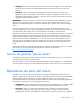
Customer self repair HP products are designed with many Customer Self Repair (CSR) parts to minimize repair time and allow for greater flexibility in performing defective parts replacement. If during the diagnosis period HP (or HP service providers or service partners) identifies that the repair can be accomplished by the use of a CSR part, HP will ship that part directly to you for replacement. There are two categories of CSR parts: • Mandatory—Parts for which customer self repair is mandatory.
• Obligatoire - Pièces pour lesquelles la réparation par le client est obligatoire. Si vous demandez à HP de remplacer ces pièces, les coûts de déplacement et main d'œuvre du service vous seront facturés. • Facultatif - Pièces pour lesquelles la réparation par le client est facultative. Ces pièces sont également conçues pour permettre au client d'effectuer lui-même la réparation.
NOTA: alcuni componenti HP non sono progettati per la riparazione da parte del cliente. Per rispettare la garanzia, HP richiede che queste parti siano sostituite da un centro di assistenza autorizzato. Tali parti sono identificate da un "No" nel Catalogo illustrato dei componenti. In base alla disponibilità e alla località geografica, le parti CSR vengono spedite con consegna entro il giorno lavorativo seguente.
anrufen und sich von einem Mitarbeiter per Telefon helfen lassen. Den Materialien, die mit einem CSRErsatzteil geliefert werden, können Sie entnehmen, ob das defekte Teil an HP zurückgeschickt werden muss. Wenn es erforderlich ist, das defekte Teil an HP zurückzuschicken, müssen Sie dies innerhalb eines vorgegebenen Zeitraums tun, in der Regel innerhalb von fünf (5) Geschäftstagen.
Centro de asistencia técnica de HP y recibirá ayuda telefónica por parte de un técnico. Con el envío de materiales para la sustitución de componentes CSR, HP especificará si los componentes defectuosos deberán devolverse a HP. En aquellos casos en los que sea necesario devolver algún componente a HP, deberá hacerlo en el periodo de tiempo especificado, normalmente cinco días laborables. Los componentes defectuosos deberán devolverse con toda la documentación relacionada y con el embalaje de envío.
periode, gewoonlijk vijf (5) werkdagen, retourneren aan HP. Het defecte onderdeel moet met de bijbehorende documentatie worden geretourneerd in het meegeleverde verpakkingsmateriaal. Als u het defecte onderdeel niet terugzendt, kan HP u voor het vervangende onderdeel kosten in rekening brengen. Bij reparatie door de klant betaalt HP alle verzendkosten voor het vervangende en geretourneerde onderdeel en kiest HP zelf welke koerier/transportonderneming hiervoor wordt gebruikt.
Serviço de garantia apenas para peças A garantia limitada da HP pode incluir um serviço de garantia apenas para peças. Segundo os termos do serviço de garantia apenas para peças, a HP fornece as peças de reposição sem cobrar nenhuma taxa. No caso desse serviço, a substituição de peças CSR é obrigatória. Se desejar que a HP substitua essas peças, serão cobradas as despesas de transporte e mão-de-obra do serviço.
Customer self repair 12
Customer self repair 13
Customer self repair 14
Customer self repair 15
Illustrated parts catalog Mechanical components Item Description Spare part number Customer self repair (on page 5) 1 Primary access panel 454347-001 Mandatory1 2 9.
Item 8 Description Spare part number Customer self repair (on page 5) g) Processor backplate* — — Media bay blank kit 459187-001 Mandatory1 (a) Hard drive blank* — — (b) Optical bay blank (12.
Optional: Optional—Teile, für die das Customer Self Repair-Verfahren optional ist. Diese Teile sind auch für Customer Self Repair ausgelegt. Wenn Sie jedoch den Austausch dieser Teile von HP vornehmen lassen möchten, können bei diesem Service je nach den für Ihr Produkt vorgesehenen Garantiebedingungen zusätzliche Kosten anfallen. 3 No: Kein—Einige Teile sind nicht für Customer Self Repair ausgelegt. Um den Garantieanspruch des Kunden zu erfüllen, muss das Teil von einem HP Servicepartner ersetzt werden.
Illustrated parts catalog 19
System components Item Description Spare part number Customer self repair (on page 5) 17 Processor — — a) 1.60-GHz Intel® Celeron® C420, 512-KB L2 cache* 454523-001 Optional2 b) 2.00-GHz Intel® Celeron® C440, 515-KB L2 cache* 454524-001 Optional2 c) 2.00-GHz Intel® Core™2 E4400, 2-MB L2 cache* 454528-001 Optional2 d) 2.40-GHz Intel® Core™2 E4600, 2-MB L2 cache* 462569-001 Optional2 e) 1.80-GHz Intel® Pentium® E2160, 1-MB L2 cache* 455623-001 Optional2 f) 3.
Item 18 Description Spare part number Customer self repair (on page 5) k) 2.66-GHz Intel® Xeon® 3075, 4-MB L2 cache* 454526-001 Optional2 l) 2.13-GHz Intel® Xeon® X3210, 8-MB L2 cache* 457020-001 Optional2 m) 2.40-GHz Intel® Xeon® X3220, 8-MB L2 cache* 454529-001 Optional2 n) 2.50-GHz Intel® Xeon® X3320, 6-MB L2 cache* 463508-001 Optional2 o) 2.66-GHz Intel® Xeon® X3350, 12-MB L2 cache* 463507-001 Optional2 p) 2.
Item 31 32 Description Spare part number Customer self repair (on page 5) d) DVD-Combo drive, 9.5-mm (4-bay hard drive cage models only)* 436952-001 Mandatory1 e) DVD-RW drive, 12.7mm 481429-001 Mandatory1 f) DVD-ROM drive, 12.
No: Non CSR—Alcuni componenti HP non sono progettati per la riparazione da parte del cliente. Per rispettare la garanzia, HP richiede che queste parti siano sostituite da un centro di assistenza autorizzato. Tali parti sono identificate da un “No” nel Catalogo illustrato dei componenti. 3 Mandatory: Zwingend—Teile, die im Rahmen des Customer Self Repair Programms ersetzt werden müssen. Wenn Sie diese Teile von HP ersetzen lassen, werden Ihnen die Versand- und Arbeitskosten für diesen Service berechnet.
Illustrated parts catalog 24
Removal and replacement procedures Required tools You need the following items for some procedures: • T-10/T-15 Torx screwdriver (included with the server) • HP Insight Diagnostics software ("HP Insight Diagnostics" on page 58) Safety considerations Before performing service procedures, review all the safety information. Preventing electrostatic discharge To prevent damaging the system, be aware of the precautions you need to follow when setting up the system or handling parts.
This symbol on an RJ-45 receptacle indicates a network interface connection. WARNING: To reduce the risk of electric shock, fire, or damage to the equipment, do not plug telephone or telecommunications connectors into this receptacle. This symbol indicates the presence of a hot surface or hot component. If this surface is contacted, the potential for injury exists. WARNING: To reduce the risk of injury from a hot component, allow the surface to cool before touching.
Server warnings and cautions Before installing a server, be sure that you understand the following warnings and cautions. WARNING: To reduce the risk of electric shock or damage to the equipment: • Do not disable the power cord grounding plug. The grounding plug is an important safety feature. • Plug the power cord into a grounded (earthed) electrical outlet that is easily accessible at all times. • Unplug the power cord from the power supply to disconnect power to the equipment.
NOTE: If the operating system automatically places the server in Standby mode, omit the next step. 3. Press the Power On/Standby button to place the server in Standby mode. When the server activates Standby power mode, the system power LED changes to amber. IMPORTANT: Pressing the UID button illuminates the blue UID LEDs on the front or rear panels. In a rack environment, this feature facilitates locating a server when moving between the front and rear of the rack. 4. Disconnect the power cords.
4. Using a T-10 Torx screwdriver, remove the secondary access panel. To replace the component, reverse the removal procedure. Primary access panel WARNING: To reduce the risk of personal injury from hot surfaces, allow the drives and the internal system components to cool before touching them. CAUTION: Do not operate the server for long periods with the access panel open or removed. Operating the server in this manner results in improper airflow and improper cooling that can lead to thermal damage. 1.
To replace the component, reverse the removal procedure. Hard drive IMPORTANT: Hot-plug capability and drive LED support are only available when a supported optional controller is installed in the server. To remove the component: 1. Back up all data on the hard drive. 2. Power down the server (on page 27). CAUTION: To prevent improper cooling and thermal damage, do not operate the server unless all bays are populated with either a component or a blank. 3. Remove the hard drive.
To replace the component, reverse the removal procedure. When adding hard drives to the server, observe the following general guidelines: • The system automatically sets all drive numbers. • If only one hard drive is used, install it in the bay with the lowest drive number. • Drives must be the same capacity to provide the greatest storage space efficiency when drives are grouped together into the same drive array. Optional storage controllers provide support for hot-plug capability and drive LEDs.
Processor air baffle To remove the component: 1. Power down the server (on page 27). 2. Remove the server from the rack (on page 28). 3. Remove the primary access panel ("Primary access panel" on page 29). 4. Remove the air baffle. To replace the component, reverse the removal procedure. Fan assembly To remove the component: 1. Power down the server (on page 27). 2. Remove the server from the rack (on page 28). 3. Remove the primary access panel ("Primary access panel" on page 29). 4.
5. Remove the fan assembly. To replace the component, reverse the removal procedure. Cache battery To remove the component: 1. Power down the server (on page 27). 2. Remove the server from the rack (on page 28). 3. Remove the primary access panel ("Primary access panel" on page 29). 4. Remove the secondary access panel (on page 28). 5. Disconnect the cache battery cable ("Battery cabling for BBWC" on page 78). 6. Remove the cache battery.
Optical drive Optical drive (12.7 mm) This procedure documents replacement of an optical drive in servers equipped with a two-bay hard drive cage. To remove the component: CAUTION: To prevent improper cooling and thermal damage, do not operate the server unless all bays are populated with either a component or a blank. 1. Power down the server (on page 27). 2. Remove the server from the rack (on page 28). 3. Remove the primary access panel ("Primary access panel" on page 29). 4.
7. Remove the interposer board. 8. Remove the 12.7-mm optical drive from the optical drive carrier. To replace the component, reverse the removal procedure. Optical drive (9.5 mm) This procedure documents replacement of an optical drive in servers equipped with a four-bay hard drive cage. To remove the component: CAUTION: To prevent improper cooling and thermal damage, do not operate the server unless all bays are populated with either a component or a blank. 1. Power down the server (on page 27). 2.
3. Remove the primary access panel ("Primary access panel" on page 29). 4. Remove the secondary access panel (on page 28). 5. Disconnect cables from the hard drive cage ("Cabling overview" on page 75). 6. Remove the 9.5-mm optical drive assembly. 7. Remove the interposer board and bracket. To replace the component, reverse the removal procedure. Bezel 1. Power down the server (on page 27). 2. Remove the server from the rack (on page 28). 3.
5. Remove the serial label pull tab by extending it, and then pressing on the underside to release it from the chassis. 6.
o Four-bay models To replace the component, reverse the removal procedure. Front I/O assembly To remove the component: 1. Power down the server (on page 27). 2. Remove the server from the rack (on page 28). 3. Remove the primary access panel ("Primary access panel" on page 29). 4. Remove the secondary access panel (on page 28). 5. Remove the bezel ("Bezel" on page 36). 6. Disconnect the front I/O assembly cable.
7. Remove the front I/O assembly. To replace the component, reverse the removal procedure. Hard drive cage To remove the component: 1. Power down the server (on page 27). 2. Remove the server from the rack (on page 28). 3. Remove the primary access panel ("Primary access panel" on page 29). 4. Remove the secondary access panel (on page 28). 5. Disconnect the front panel/LED cable from the system board. ("Cabling overview" on page 75) 6. Disconnect the hard drive cables from the system board.
13. o Two-bay models o Four-bay models Remove the SAS/SATA backplane ("SAS/SATA backplane" on page 40). To replace the component, reverse the removal procedure. SAS/SATA backplane To remove the component: 1. Power down the server (on page 27). 2. Remove the server from the rack (on page 28). 3. Remove the primary access panel ("Primary access panel" on page 29). 4. Remove the secondary access panel (on page 28). 5. Disconnect the hard drive cables from the system board.
6. Disconnect cables from any other devices installed in the hard drive cage, if installed. 7. Remove the cache battery, if installed ("Cache battery" on page 33). 8. Remove all hard drives ("Hard drive" on page 30). 9. Remove the hard drive cage ("Hard drive cage" on page 39). 10. Remove the backplane: o Two-bay models o Four-bay models To replace the component, reverse the removal procedure.
To remove the component: 1. Power down the server (on page 27). 2. Remove the server from the rack (on page 28). 3. Remove the primary access panel ("Primary access panel" on page 29). 4. Disconnect any internal or external cables connected to any existing expansion boards. 5. Remove the PCI riser board assembly. To replace the component, reverse the removal procedure. PCI Express or PCI-X riser board To remove the component: 1. Power down the server (on page 27). 2.
6. Remove the riser board. To replace the component, reverse the removal procedure. Expansion boards To remove the component: 1. Power down the server (on page 27). 2. Remove the server from the rack (on page 28). 3. Remove the primary access panel ("Primary access panel" on page 29). 4. Remove the PCI riser board assembly ("PCI riser board assembly" on page 41). 5. Remove any installed expansion boards. To replace the component, reverse the removal procedure.
Power supply To remove the component: 1. Power down the server (on page 27). 2. Remove the server from the rack (on page 28). 3. Remove the primary access panel ("Primary access panel" on page 29). 4. Disconnect the removable media and hard drive power cables from the hard drive backplane. 5. Disconnect the auxiliary power supply cable and the main power supply cable from the system board. 6. Remove the power supply. To replace the component, reverse the removal procedure.
b. Fully loosen the screws to free the heatsink, being careful not to remove the screw assemblies from the heatsink. 6. Remove the heatsink. To replace the component: IMPORTANT: When replacing the heatsink, check the label on top to be sure the heatsink is properly oriented. 1. Use the alcohol swab to remove all the existing thermal grease from the processor. Allow the alcohol to evaporate before continuing. CAUTION: After the cover is removed, do not touch the thermal interface media.
2. Remove the protective cover from the heatsink. CAUTION: Heatsink retaining screws should be tightened or loosened in diagonally opposite pairs (in an "X" pattern). Do not overtighten the screws as this can damage the board, connectors, or screws. Use the wrench supplied with the system to reduce the possibility of overtightening the screws. 3. Install the heatsink. 4. Install the air baffle ("Processor air baffle" on page 32). 5. Install the access panel ("Primary access panel" on page 29).
WARNING: To reduce the risk of personal injury from hot surfaces, allow the drives and the internal system components to cool before touching them. CAUTION: To prevent possible server malfunction, do not mix processors of different speeds or cache sizes. 1. Power down the server (on page 27). 2. Remove the server from the rack (on page 28). 3. Remove the primary access panel ("Primary access panel" on page 29). 4. Remove the air baffle ("Processor air baffle" on page 32). 5.
IMPORTANT: Be sure the processor remains inside the processor installation tool. 1. If the processor has separated from the installation tool, carefully re-insert the processor in the tool. 2. Align the processor installation tool with the socket and install the spare processor. CAUTION: The processor is designed to fit one way into the socket. Use the alignment guides on the processor and socket to properly align the processor with the socket. Refer to the server hood label for specific instructions.
3. Press down firmly until the processor installation tool clicks and separates from the processor, and then remove the processor installation tool. 4. Close the processor retaining latch and the processor socket retaining bracket. 5. Clean the old thermal grease from the heatsink with the alcohol swab. Allow the alcohol to evaporate before continuing.
6. Apply all the grease to the top of the processor in one of the following patterns to ensure even distribution: CAUTION: Heatsink retaining screws should be tightened or loosened in diagonally opposite pairs (in an "X" pattern). Do not overtighten the screws as this can damage the board, connectors, or screws. Use the wrench supplied with the system to reduce the possibility of overtightening the screws. 7. Install the heatsink. 8. Install the air baffle ("Processor air baffle" on page 32). 9.
3. Remove the primary access panel ("Primary access panel" on page 29). 4. Remove the iLO connector module. To replace the component, reverse the removal procedure. System board To remove the component: 1. Power down the server (on page 27). 2. Remove the server from the rack (on page 28). 3. Remove the primary access panel ("Primary access panel" on page 29). 4. Remove the secondary access panel (on page 28). 5. Remove the PCI riser board assembly ("PCI riser board assembly" on page 41). 6.
14. Open the processor retaining latch and the processor socket retaining bracket on the failed system board. 15. Using your fingers, remove the processor from the failed system board. CAUTION: To avoid damage to the system board: • Do not touch the processor socket contacts. • Always install the processor socket cover after removing the processor from the socket. • Do not tilt or slide the processor when lowering the processor into the socket.
17. Remove the failed system board. To replace the system board: 1. Install the spare system board in the server. 2. Prepare the processor socket on the spare system board: a. Open the processor retaining latch and the processor socket retaining bracket.
b. Remove the processor socket protective cover. 3. Install the processor socket cover onto the processor socket of the failed system board. 4. Install the processor on the spare system board. CAUTION: The processor is designed to fit one way into the socket. Use the alignment guides on the processor and socket to properly align the processor with the socket. Refer to the server hood label for specific instructions.
5. Close the processor retaining latch and the processor socket retaining bracket. 6. Clean the old thermal grease from the heatsink and the top of the processor with the alcohol swab. Allow the alcohol to evaporate before continuing. 7. Apply all the grease to the top of the processor in one of the following patterns to ensure even distribution: CAUTION: Heatsink retaining screws should be tightened or loosened in diagonally opposite pairs (in an "X" pattern).
8. Install the heatsink. IMPORTANT: To ensure proper cooling, be sure the processor air baffle is installed at all times (if applicable). 9. Install all components removed from the failed system board. IMPORTANT: Install all components with the same configuration that was used on the failed system board. 10. Install the secondary access panel ("Remove the secondary access panel" on page 28). 11. Install the primary access panel ("Primary access panel" on page 29). 12. Power up the server.
Battery If the server no longer automatically displays the correct date and time, you may need to replace the battery that provides power to the real-time clock. Under normal use, battery life is 5 to 10 years. WARNING: The computer contains an internal lithium manganese dioxide, a vanadium pentoxide, or an alkaline battery pack. A risk of fire and burns exists if the battery pack is not properly handled. To reduce the risk of personal injury: • Do not attempt to recharge the battery.
Diagnostic tools Troubleshooting resources The HP ProLiant Servers Troubleshooting Guide provides procedures for resolving common problems and comprehensive courses of action for fault isolation and identification, error message interpretation, issue resolution, and software maintenance on ProLiant servers and server blades. This guide includes problemspecific flowcharts to help you navigate complex troubleshooting processes. To view the guide, select a language: • English (http://www.hp.
Survey functionality is installed with every SmartStart-assisted HP Insight Diagnostics installation, or it can be installed through the HP PSP. NOTE: The current version of SmartStart provides the memory spare part numbers for the server. To download the latest version, see the HP website (http://www.hp.com/support). Manual ROMPaq disaster recovery 1. Create a ROMPaq diskette. For more information, see the HP website (http://www.hp.com/support). 2. Power down the server (on page 27). 3.
Array Diagnostic Utility The HP Array Diagnostics Utility is a web-based application that creates a report of all HP storage controllers and disk drives. This report provides vital information to assist in identifying faults or conditions that may require attention. ADU can be accessed from the SmartStart CD or downloaded from the HP website (http://www.hp.com).
from a USB drive key installed in the front internal connector, avoiding issues of clearance on the front of the rack and physical access to secure data. For additional security, you can individually disable the front, rear, and internal USB connectors through RBSU. Disabling the rear USB connectors in RBSU disables both rear USB ports.
Component identification Front panel components Front panel components (standard configuration) Item Description 1 Hard drive bay 1 2 Hard drive bay 2 3 Serial label pull tab 4 12.
Front panel components (optional hard drive cage configuration) Item Description 1 Hard drive bay 1 2 Hard drive bay 2 3 9.
Front panel LEDs and buttons Front panel LEDs and buttons (standard configuration) Item Description Status 1 12.7-mm optical drive activity LED Green = Drive activity is normal. Amber = Drive failure has occurred. Off = No drive activity exists. 2 UID button/LED Blue = Identification is activated. Flashing blue = System is being remotely managed. Off = Identification is deactivated. 3 Internal health LED Green = System health is normal. Amber = System health is degraded.
Item Description Status 6 Drive activity LED Green = Drive activity is normal. Amber = Drive failure has occurred. Off = No drive activity exists. 7 Power On/Standby button and system power LED Green = System is on. Amber = System is shut down, but power is still applied. Off = Power cord is not attached or power supply failure has occurred. Front panel LEDs and buttons (optional hard drive cage configuration) Item Description Status 1 UID button/LED Blue = Identification is activated.
Item Description Status 4 NIC 2 link/activity LED Green = Network link exists. Flashing green = Network link and activity exist. Off = No network link exists. If power is off, the front panel LED is not active. View the LEDs on the RJ-45 connector. See "Rear panel LEDs (on page 68)." 5 Drive activity LED Green = Drive activity is normal. Amber = Drive failure has occurred. Off = No drive activity exists. 6 Power On/Standby button and system power LED Green = System is on.
SATA device numbers (optional hard drive cage configuration) Rear panel components For this server model, PCI expansion slots 1-3 and 6-7 are reserved.
Item Description 8 UID button/LED 9 Video connector 10 Dedicated iLO 2 management port (optional) 11 10/100/1000 NIC 1/shared iLO 2 management port 12 Keyboard connector PCI expansion slot definitions For this server model, PCI expansion slots 1-3 and 6-7 are reserved. Slot Type Length Connector Interconnect 4 PCI Express Full x8 x8 4 Optional PCI-X Full 133 MHz/3.3. V 64 bit 5 PCI Express* Half x8 x1 *x8 PCI Express cards are supported, but will run at x1 speeds.
System board components For this server, some system board slots and connectors are reserved.
Item Description 23 Reserved 24 SATA connector 5 (optical drive)* 25 Internal USB option connector 26 Reserved 27 SATA connector 3 (hard drive) 28 SATA connector 1 (hard drive) 29 Parallel option connector 30 Serial option connector 31 Reserved 32 PCI Express expansion slot 4 33 PCI Express expansion slot 5** 34 Reserved 35 Reserved 36 Reserved 37 Dedicated iLO2 optional module connector * The server supports one optical drive that can be connected to either SATA connector 5
NMI functionality An NMI crash dump enables administrators to create crash dump files when a system is hung and not responding to traditional debug mechanisms. Crash dump log analysis is an essential part of diagnosing reliability problems, such as hangs in operating systems, device drivers, and applications. Many crashes freeze a system, and the only available action for administrators is to cycle the system power.
Item LED description Status 4 Fan 2 failure Amber = Fan 2 has failed or is missing. Off = Normal 5 Fan 3 failure Amber = Fan 3 has failed or is missing. Off = Normal 6 PCI fan failure Amber = PCI fan has failed or is missing. Off = Normal 7 Overtemperature Amber = System has reached a cautionary or critical temperature level. 8 DIMM 4 failure Amber = DIMM has failed or is missing. Off = Normal 9 DIMM 3 failure Amber = DIMM has failed or is missing.
System LED and Color Internal Health LED Color Status Amber • DIMM in slot X has reached single-bit correctable error threshold. • DIMM in slot X is in a pre-failure condition. • DIMM in slot X is an unsupported type, but valid memory exists in another bank. DIMM failure, all slots in one bank (amber) Red No valid or usable memory is installed in the system. Overtemperature (amber) Amber The Health Driver has detected a cautionary temperature level.
Fan locations Standard configurations include either three or four fans.
Cabling Cabling overview This section provides guidelines that help you make informed decisions about cabling the server and hardware options to optimize performance. Server cabling CAUTION: When routing cables, always be sure that the cables are not in a position where they can be pinched or air flow can be blocked. IMPORTANT: Route the cables without blocking the airflow or other installed components. Use the cable clips installed in the chassis to manage cable routing.
Embedded SATA controller cabling (optional hard drive cage configuration) CAUTION: When routing cables, always be sure that the cables are not in a position where they can be pinched or air flow can be blocked. Optional SAS controller cabling Optional SAS controller cabling (standard configuration) CAUTION: When routing cables, always be sure that the cables are not in a position where they can be pinched or air flow can be blocked.
Optional SAS controller cabling (optional hard drive cage configuration) CAUTION: When routing cables, always be sure that the cables are not in a position where they can be pinched or air flow can be blocked.
Battery cabling for BBWC BBWC battery cabling to an optional controller in slot 4 BBWC battery cabling to an optional controller in slot 5 Cabling 78
Optional internal USB cabling Cabling 79
Specifications Environmental specifications Specification System inlet temperature Value 1 Operating 10°C to 35°C (50°F to 90°F) Non-operating -30°C to 60°C (-22°F to 140°F) Maximum rate of temperature change Operating 10°C/hr (18°F/hr) 2,3 Non-operating 20°C/hr (36°F/hr) Relative humidity (noncondensing) Operating 10% to 90% Non-operating 5% to 95% Maximum wet bulb temperature (non-condensing) Operating 28°C (82.4°F) Non-operating 38.7°C (101.
Specification Value Weight (maximum configuration: all hard drives, power supplies, and processors installed) 15.20 kg (33.50 lb) Weight (minimum configuration: one hard drive, power supply, and processor installed) 11.79 kg (26.0 lb) Input requirement1 Rated line voltage 90 VAC to 264 VAC Rated input frequency 47 Hz to 63 Hz Rated input current 6.
Acronyms and abbreviations ACU Array Configuration Utility BIOS Basic Input/Output System iLO Integrated Lights-Out LED light-emitting diode NIC network interface controller NMI non-maskable interrupt NVRAM non-volatile memory PCI peripheral component interface PCI Express Peripheral Component Interconnect Express PCI-X peripheral component interconnect extended POST Power-On Self Test PPM processor power module Acronyms and abbreviations 82
RBSU ROM-Based Setup Utility ROM read-only memory SAS serial attached SCSI SATA serial ATA SCSI small computer system interface SIM Systems Insight Manager UID unit identification USB universal serial bus Acronyms and abbreviations 83
Index 1 12.7-mm optical drive 34 9 9.
L LEDs LEDs, LEDs, LEDs, LEDs, LEDs, LEDs, 62, 64, 71, 72 front panel 64 hard drive 64 NIC 68 rear panel 68 system board 71 troubleshooting 72 M management tools 58 mechanical components 16 memory dump 71 N NIC LEDs 64, 68 NMI switch 71 O operating system crash 71 optical device 62 optical drive 34 optional SAS controller cabling 76 overtemperature LED 71 P part numbers 16, 20 PCI Express 67 PCI Express riser boards 42 PCI riser board 41 power LEDs, system 64 Power On/Standby button 27, 62, 64 power su