
HP ProLiant DL320s Server Maintenance and Service Guide

Server component identification 44
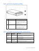
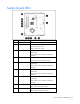
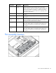
System board components
Item
Description Item Description
1 PCI Express x8 connector 10 Fan 3 connector
2 PCI Express x1 connector 11 Fan 4 connector
3 System maintenance switch
(on page 44)
12 Main power connector
4 NMI switch ("NMI
functionality" on page 45)
13 Processor socket
5 Battery 14 Auxiliary power connector
6 Front panel LED board
connector
15 DIMM slot 1 (bank A)
7 Internal USB connector 16 DIMM slot 2 (bank B)
8 Fan 1 connector 17 DIMM slot 3 (bank A)
9 Fan 2 connector 18 DIMM slot 4 (bank B)
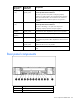
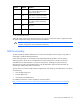
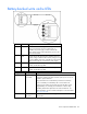
System maintenance switch
Position Default Function
S1 Off Off = iLO 2 security is enabled
On = iLO 2 security is disabled
S2 Off Off = Normal operation
On = RBSU will not commit any
configuration changes *
S3 Off Reserved