
ProLiant DL320 Generation 3 Server User Guide
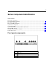
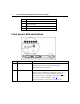
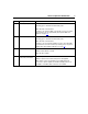
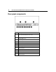
Table Of Contents
- HP ProLiant DL320 Generation 3 Server User Guide
- Notice
- Contents
- Server component identification
- Server operations
- Powering up the server
- Powering down the server
- Preparation procedures
- Extending the server from the rack
- Removing the access panel
- Installing the access panel
- Removing the PCI riser board assembly
- Installing PCI riser board assembly
- Removing the hot-plug SATA backplane
- Removing the fan assembly
- Installing the fan assembly
- Server setup
- Hardware options installation
- Server cabling
- Server software and configuration utilities
- Battery replacement
- Troubleshooting
- Electrostatic discharge
- Regulatory compliance notices
- Regulatory compliance identification numbers
- Federal Communications Commission notice
- Declaration of conformity for products marked with the FCC logo, United States only
- Modifications
- Cables
- Mouse compliance statement
- Canadian notice (Avis Canadien)
- European Union regulatory notice
- Japanese notice
- BSMI notice
- Korean notice A&B
- Laser compliance
- Battery replacement notice
- Taiwan battery recycling notice
- Power cord statement for Japan
- Server specifications
- Technical support
- Acronyms and abbreviations
- Index
8 HP ProLiant DL320 Generation 3 Server User Guide
Item Description
4 Diskette drive bay
5 Optical device bay
6 Front USB port
7 Power button
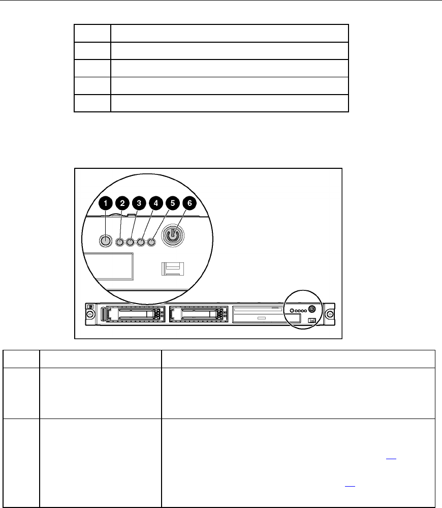
Front panel LEDs and buttons
Item Description Status
1 UID button/LED Blue = Identification is activated.
Flashing blue = System is being remotely managed.
Off = Identification is deactivated.
2 Internal health LED Green = System health is normal.
Amber = System is degraded. To identify the component in a
degraded state, refer to system board LEDs (on page 14
).
Red = System critical. To identify the component in a critical
state, refer to system board LEDs (on page 14
).
Off = System health is normal (when in standby mode).