
ProLiant DL320 Generation 3 Server User Guide
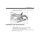
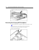
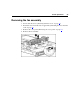
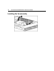
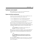
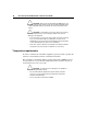
Table Of Contents
- HP ProLiant DL320 Generation 3 Server User Guide
- Notice
- Contents
- Server component identification
- Server operations
- Powering up the server
- Powering down the server
- Preparation procedures
- Extending the server from the rack
- Removing the access panel
- Installing the access panel
- Removing the PCI riser board assembly
- Installing PCI riser board assembly
- Removing the hot-plug SATA backplane
- Removing the fan assembly
- Installing the fan assembly
- Server setup
- Hardware options installation
- Server cabling
- Server software and configuration utilities
- Battery replacement
- Troubleshooting
- Electrostatic discharge
- Regulatory compliance notices
- Regulatory compliance identification numbers
- Federal Communications Commission notice
- Declaration of conformity for products marked with the FCC logo, United States only
- Modifications
- Cables
- Mouse compliance statement
- Canadian notice (Avis Canadien)
- European Union regulatory notice
- Japanese notice
- BSMI notice
- Korean notice A&B
- Laser compliance
- Battery replacement notice
- Taiwan battery recycling notice
- Power cord statement for Japan
- Server specifications
- Technical support
- Acronyms and abbreviations
- Index

22 HP ProLiant DL320 Generation 3 Server User Guide
1. Power down the server if the standard cable management solution is installed
("Powering down the server" on page 19
).
NOTE: If the optional cable management arm is installed, you can
extend the server and perform hot-plug installation or maintenance
procedures without powering down the server.
2. Extend the server from the rack, if applicable ("Extending the server from the
rack" on page 21
).
3. Use a screwdriver to remove the captive screw.
4. Slide the access panel back and lift it off the server.
Installing the access panel
1. Place the access panel on top of the server, allowing it to extend past the rear
of the server approximately 10 mm (0.39 in).
2. Slide the access panel forward to lock, and tighten the captive screw to
secure the access panel to the server.
Removing the PCI riser board assembly
CAUTION: To prevent damage to the server or expansion
boards, power down the server and remove all AC power cords before
removing or installing the PCI riser cage.
1. Power down the server ("Powering down the server" on page 19).
2. Extend the server from the rack, if applicable ("Extending the server from the
rack" on page 21
).
3. Remove the access panel ("Removing the access panel" on page 21
).
4. Remove the PCI riser board assembly:
a. Disconnect any internal or external cables connected to any existing
expansion boards.
b. Loosen the two PCI riser board assembly thumbscrews.