
HP ProLiant DL320 Generation 2 Server Setup and Installation Guide

Installing Hardware Options
Identifying System Board Components
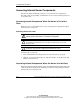
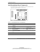
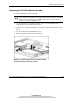
Use the following figure and table to identify the system board connectors and
components for option installation or service events.
Figure 3-4: Identifying system board components
Table 3-1: System Board Connectors and Components
Location Component Location Component
1 Unit Identification (UID)
LED/button
7 USB connector 2
2 Serial (top) and video (bottom)
connectors
8 64-bit 33-MHz PCI riser board
assembly connector
3 Mouse (top) and keyboard
(bottom) connectors
9 System configuration switch
(SW1)
4 RJ-45 fast Ethernet connectors
for NIC 1 (bottom) and NIC 2
(top)
10 ATA controller (secondary)
5 Slotless SCSI module slot 11 Power connector
6 USB connector 1 12 System battery
continued
3-6 HP ProLiant DL320 Generation 2 Server Setup and Installation Guide
HP CONFIDENTIAL
Writer: Anna Roberts File Name: d-ch3 Installing Hardware Options.doc
Codename: MoonStar Part Number: 293166-002 Last Saved On: 1/31/03 11:16 AM