
HP ProLiant DL165 G7 Server Installation Sheet


7
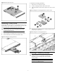
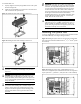
To install the heat sink:
1. Properly align the heat sink spring-loaded screws to the system
board mounting holes.
2. Tighten the spring-loaded screws clockwise to secure the heat
sink connection to the system board.
Figure 11 Installing the Heat Sink Assembly of Processor 1
Figure 12 Installing the Heat Sink Assembly of Processor 2
CAUTION: Be sure that the heat sink sits squarely on the
processor, or overheating and damage to the processor
may occur.
CAUTION: When installing heat sinks of processor 1, it is
recommended to put the heat sinks with the 15-fin side
facing the DIMMs; When installing heat sinks of processor
2, it is recommended to put the heat sinks with the 2-fin side
facing the DIMMs.
CAUTION: Do not over-tighten the spring-loaded screws to
prevent them from breaking off. A maximum torque of 7
inch-lb is set for each screw. Rotate the heat sink a few
degrees to the left and right to break the bonding of the
thermal grease before removing the heat sink from the
processor.
IMPORTANT: If the heat sink has been removed for any
reason, it is critical that you apply more thermal interface
material to the integrated heat spreader on the processor
to ensure proper thermal bonding between the processor
and the heat sink. Clean the contact surface of both the
processor and heat sink with an alcohol pad, then re-apply
an HP-approved thermal interface material before
reinstalling the processor. Use a pattern of five dots when
applying the thermal interface material—one dot in the
center, and one dot at each corner.
CAUTION: For proper cooling, do not operate the server
without the top cover, air baffle, expansion slot covers, or
blanks installed. For additional information, see the user
guide. If hot-plug components are supported, minimize the
amount of time the top cover is removed.
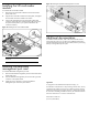
Installing the system fans
For servers installed with one or two processors, the system fans should
be installed differently according to the figures below:
Figure 13 Installing the System Fans for One Processor Configuration
(The system fans should be installed on the 2
nd
, 4
th
, 5
th
and 6
th
system
fan locations)
Figure 14 Installing the System Fans with Redundancy for Two
Processors Configuration (The redundant fan functions are supported
by the system fan 1, system fan 3, and system fan 7 when installed)