
HP ProLiant DL165 G6 Server Maintenance and Service Guide


Removal and Replacement Procedures 43
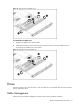
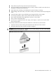
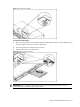
Cable Connections
The following table provides information about switching power supply cable connector labels.
Table 9
Cable connections
Cable To Cable Designator
Switching Power Supply System board 24-pin power connector P1
Switching Power Supply System board 8-pin power connector P2
Switching Power Supply System board 4-pin power connector P3
Switching Power Supply Backplane P10
Switching Power Supply Backplane P11
Switching Power Supply Optical disc drive P5
Switching Power Supply System board Power Supply
Management Interface connector
RPS
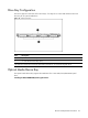
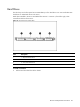
The following table provides the system board designators that various cables plug into. For more
detailed information about system board components, see system board components on page 27.
Table 10
Cable connections
Cable To System Board Designator
Internal USB connector USB J21
18-Pin front panel connector Front panel P10
SATA1 connector SATA1 SATA1
SATA2 connector SATA2 SATA2
SATA3 connector SATA3 SATA3
SATA4 connector SATA4 SATA4
Front USB 2.0 cable header USB P11
5-Pin system fan6 header System fan6 P19
5-Pin system fan5 header System fan5 P17
5-Pin system fan4 header System fan4 P15
5-Pin system fan3 header System fan3 P13
5-Pin system fan2 header System fan2 P18
5-Pin system fan1 header System fan1 P12
4-pin power connector Power supply P24
24-pin power connector Power supply P21
8-pin power connector Power supply P23