
HP ProLiant DL165 G5p Server Maintenance and Service Guide

Contents 29
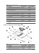
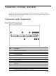
Designator Description
11 XU3 Internal USB connector
12 J21 Password jumper
13 P10 18-Pin front panel port
14 P19 5-Pin system fan 6 header
15 J25 IDE channel
16 SATA SATA1,2,3,4 connector
17 P11 Front USB 2.0 cable header
18 P17 5-Pin system fan 5 header
19 P15 5-Pin system fan 4 header
20 P13 5-Pin system fan 3 header
21 P18 5-Pin system fan 2 header
22 XU1 Processor 0 socket
23 XMM Processor 0 DIMM slots
24 P12 5-Pin system fan1 header
25 P24 4-pin power connector
26 P21 24-pin power connector
27 P23 8-pin power connector
28 XU2 Processor 1 socket
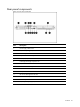
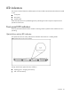
Jumpers – Password and Chassis ID
The system board password (P20) chassis ID1(P26) and chassis ID2(P27) jumpers. Table 4 describes
the jumper settings.
Table 4
System configuration switch settings
Jumper Status
P20 1-2, password enable
P26 1-2, default setting
P27 2-3, default setting
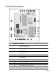
System Switches
Clear CMOS Button (SW4)
The system board has a system configuration (CMOS) button (SW4). To clear system configuration,
remove power cord and press the CMOS button for seconds.