HP ProLiant DL160se G6 Server Software Configuration Guide Part number 516740-001 First edition April 2009
Legal notices © Copyright 2009 Hewlett-Packard Development Company, L.P. The information contained herein is subject to change without notice. The only warranties for HP products and services are set forth in the express warranty statements accompanying such products and services. Nothing herein should be construed as constituting an additional warranty. HP shall not be liable for technical or editorial errors or omissions contained herein.
Contents System BIOS configuration ...................................................................................................................... 4 System BIOS overview .............................................................................................................................. 4 AMIBIOS software ................................................................................................................................... 4 AMIBIOS Setup Utility.................................
System BIOS configuration This chapter describes the basic functions of the AMIBIOS software. System BIOS overview A Basic Input/Output System, or BIOS, is a set of programs permanently stored in an EEPROM chipset located on the system board. These programs serve as an interface between the server’s hardware components and its operating system.
• When a configuration error is detected by the system and you are prompted by a "Run Setup" message to make changes to the BIOS settings. NOTE: If you repeatedly receive “Run Setup” messages, the battery located on the system board may be defective. In this case, the system cannot retain configuration values in CMOS. Ask a qualified technician for assistance. The Setup Utility loads the configuration values in a battery-backed nonvolatile memory called CMOS RAM.
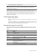
Setup Utility menus The Setup Utility menu bar displays the five primary menu selections. For detailed information and screenshots of these Setup Utility menus and their related submenus, refer to the following sections. Main menu Figure 1 Main menu ROM-based Setup Utility Boot Security Exit System Overview User [ENTER], [TAB] or [SHIFT-TAB] to Product Name: Proliant DL160se G6 select a field.
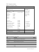
Table 2 Main menu fields Field Description Options Product Name Display the product name of the system. ProLiant BIOS Display the BIOS family. Build Date Display the date when this version of BIOS was built. ROM ID Display the ID of the ROM. Processor Display detailed processor information. System Memory Displays the amount of conventional memory detected during POST. System Time Adjust the system time. System Date Adjust the system date.
Advanced menu Figure 2 Advanced menu ROM-based Setup Utility Main Boot Security Exit Advanced Settings Custom: Allow to WARNING: Setting wrong values in below sections configure Efficiency may cause system to malfunction. /Performance related items individually.
Table 3 Advanced menu fields Field Description CPU Bridge Configuration Configure CPU Bridge chipset settings. SATA Configuration Configure SATA device settings. SuperIO Configuration Configure PILOT Super I/O chipset settings. USB Configuration Configure USB controller settings. PCI Configuration Configure PCI settings. PCI Express Configuration Configure PCI Express settings. IPMI Configuration Configure. IPMI 2.0 settings.
CPU Configuration submenu Figure 3 CPU Configuration submenu ROM-based Setup Utility Configure advanced CPU settings When enabled, a VMM Module Version: 01.01 can utilize the Manufacturer: provided by Intel(R) additional HW Caps Intel Intel(R) Xeon(R) CPU X5570 @ 2.93GHz Virtualization Tech. Frequency: 2.93GHz Note: A full reset is BCLK Speed: 133MHz required to change Cache L1: 128 KB the setting.
Table 4 CPU Configuration submenu fields Field Description Options Hardware Prefetcher Enable the hardware components that are used in conjunction with software programs to prefetcher data in order to shorten execution cycles and maximize data processing efficiency. Enabled Disable the hardware components that are used in conjunction with software programs to prefetcher data in order to shorten execution cycles and maximize data processing efficiency.
CPU Bridge Configuration submenu Figure 4 CPU Bridge Configuration submenu ROM-based Setup Utility CPU Bridge Chipset Configuration submenu To transfer the QPI CPU Revision D0 Links to full-speed Current QPI Frequency 6.
Table 5 CPU Bridge Configuration submenu fields Field QPI L0s and L1 Description Options Transit the links to 4.800GT when transitioning the links to full-speed. 4.800GT Transit the links to 5.866GT when transitioning the links to full-speed. 5.866GT Transit the links to 6.400GT when transitioning the links to full-speed. 6.400GT Enabled L0s and L1. Enabled Disabled L0s and L1. Disabled Memory Frequency Transit the memory frequency to the maximum speed.
SATA Configuration submenu Figure 5 SATA Configuration submenu ROM-based Setup Utility Options SATA Configuration SATA#1 Controller Mode [Compatible] SATA#2 Controller Mode [Enabled] Disabled Compatible RAID >Primary IDE Master: [Not Detected] >Primary IDE Slave: [Not Detected] >Secondary IDE Master: [Not Detected] >Secondary IDE Slave: [Not Detected] >Third IDE Master: [Not Detected] >Fourth IDE Master: [Not Detected] AHCI ←→ Select Screen ↑↓ Select Item +- Change Option F1
Table 6 SATA Configuration submenu fields Field Description Options Disable SATA#2 Controller. Disabled Primary IDE Master Primary IDE Master not detected. Not Detected Primary IDE Slave Primary IDE slave not detected. Not Detected Secondary IDE Master Secondary IDE Master not detected. Not Detected Secondary IDE Slave Secondary IDE slave not detected. Not Detected Third IDE Master Third IDE Master not detected. Not Detected Fourth IDE Master Fourth IDE Master not detected.
Super IO Configuration submenu Figure 6 Super IO Configuration submenu ROM-based Setup Utility Allows BIOS to Select Configure PILOT Super IO Chipset Embedded Serial Port Embedded Serial Port Address [3F8/IRQ4] Base Addresses. ←→ Select Screen ↑↓ Select Item +- Change Option F1 General Help F10 Save and Exit ESC Exit V02. 61(C) Copyright 1985-2006, American Megatrends, Inc.
Table 7 Super IO submenu fields Field Description Options Set this value to allow the serial port to use 3F8 as its I/O port address and IRQ 4 for the interrupt address. This is the default setting. The majority of serial port 1 or COM1 ports on computer systems use IRQ4 3F8/IRQ4 and I/O Port 3F8 as the standard setting. The most common serial device connected to this port is a mouse. If the system will not use a serial device, it is best to set this port to Disabled.
USB Configuration submenu Figure 7 USB Configuration submenu ROM-based Setup Utility Options USB Configuration Module Version – 2.24.3-13.4 Disabled Enabled USB Devices Enabled: 2 Keyboards, 2 Mouse, 1 Drive USB Functions [Enabled] Legacy USB Support [Enabled] USB 2.0 Controller [Enabled] USB 2.
Table 8 USB Configuration submenu fields Field Description Options BIOS EHCI Hand-Off Set this value to enable EHCI hand-off support. This is the default value. Enabled Set this value to disable EHCI hand-off support. This is used when your OS does not support EHCI hand-off. Disabled Hot-plug USB FDD Support Set this value to enable Hot-plug USB FDD support. Enabled Clear this value to disable Hot-plug USB FDD support.
PCI Configuration submenu Figure 8 PCI Configuration submenu ROM-based Setup Utility Select which graphics PCI Configuration controller to use as Embedded VGA Control [Auto Detect] the primary boot device. Embedded NIC Port 1 Control [Enabled] Embedded NIC Port 1 PXE [Enabled] Embedded NIC Port 2 Control [Enabled] Embedded NIC Port 2 PXE [Disabled] Wake-On LAN [Enabled] ←→ Select Screen ↑↓ Select Item +- Change Option F1 General Help F10 Save and Exit ESC Exit V02.
Table 9 PCI Configuration submenu fields Field Description Options Disable Onboard NIC2. Disabled Embedded NIC Port 2 PXE Enable Onboard NIC2 PXE. Enabled Disable Onboard NIC2 PXE. Disabled Allow wake up in S4/S5 over LAN. This is the default setting. Enabled Disabled Wake-On LAN in S4/S5.
PCI Express Configuration submenu Figure 9 PCI Express Configuration submenu ROM-based Setup Utility PCI Express Configuration Active State Power-Management [Disabled] PCI Express Gen2 [Gen2] ←→ Select Screen ↑↓ Select Item F1 General Help F10 Save and Exit ESC Exit V02. 61(C) Copyright 1985-2006, American Megatrends, Inc. Table 10 PCI Express Configuration submenu fields Field Description Options Active State Power Management Enable the PCIE ports to enter L0s and/or L1 states.
IPMI Configuration submenu Figure 10 IPMI Configuration submenu ROM-based Setup Utility InPut for Set LAN IPMI 2.0 Configuration Configuration command. Status of BMC Working NOTE: - BMC Firmware Revision 09.13 BMC/IPMI FW Date: Jan/09/2009 this group may take BMC SDR Version: 2.16.0.36 considerable amount of Each question in time.
Table 11 IPMI Configuration submenu fields Field Description Options Watch Dog Configuration Access the submenu to configure Option of Watch Dog Configuration. Hardware Health Status Access the submenu to view Hardware Health Status.
BIOS Serial Console Configuration submenu Figure 11 BIOS Serial Console Configuration submenu ROM-based Setup Utility Configure BIOS Serial Console type and parameters Select BIOS Serial Console type. BIOS Serial Console [Disabled] ←→ Select Screen ↑↓ Select Item +- Change Option F1 General Help F10 Save and Exit ESC Exit V02. 61(C) Copyright 1985-2006, American Megatrends, Inc.
Trusted Computing submenu Figure 12 Trusted Computing submenu ROM-based Setup Utility Trusted Computing TPM Status No Present ←→ Select Screen ↑↓ Select Item F1 General Help F10 Save and Exit ESC Exit V02. 61(C) Copyright 1985-2006, American Megatrends, Inc. Table 13 Trusted Computing submenu fields Field Description Options TPM Status TPM not present No Present Display TPM Status.
Boot menu Figure 13 Boot menu ROM-based Setup Utility Main Advanced Security Exit Configure Settings Boot Settings during System Boot. > Boot Settings Configuration >Standard Boot Order >Hard Disk Drives USB Device Boot Priority [High] Restore on AC Power Loss [Last State] ←→ Select Screen ↑↓ Select Item Enter Go to Sub Screen F1 General Help F10 Save and Exit ESC Exit V02. 61 (C) Copyright 1985-2006, American Megatrends, Inc.
Table 14 Boot menu fields Field Description Options Power on the server after power loss. Power on Restore last state after power loss.
Boot Settings Configuration submenu Figure 14 Boot Setting Configuration submenu ROM-based Setup Utility Allows BIOS to skip Boot Settings Configuration certain tests while Quick Boot [Enabled] booting. This will Quiet Boot [Enabled] decrease the time Num Lock [Enabled] needed to boot the system. ←→ Select Screen ↑↓ Select Item +F1 Change Option General Help F10 Save and Exit ESC Exit V02. 61 (C) Copyright 1985-2006, American Megatrends, Inc.
Table 15 Boot Settings Configuration submenu fields Field Description Options This option does not enable the keyboard Num Lock automatically. To use the numeric keypad, press the Num Lock key located on the upper left-hand corner of the numeric keypad. The Num Lock LED on the keyboard will light up when Num lock is engaged. This is the default setting.
Standard Boot Order submenu Figure 15 Standard Boot Order submenu ROM-based Setup Utility Specifies the boot Standard Boot Order sequence from the 1st Boot Device [Hard Drive] 2nd Boot Device [Network:IBA GE Slo] available devices. A device enclosed in parenthesis has been disabled in the corresponding type menu. ←→ Select Screen ↑↓ Select Item +F1 Change Option General Help F10 Save and Exit ESC Exit V02. 61 (C) Copyright 1985-2006, American Megatrends, Inc.
Hard Disk Drives submenu Figure 16 Hard Disk Drives submenu ROM-based Setup Utility Specifies the boot Hard Disk Drives sequence from the 1st Drive [USB: SanDisk USB F1] available devices. ←→ Select Screen ↑↓ Select Item +F1 Change Option General Help F10 Save and Exit ESC Exit V02. 61 (C) Copyright 1985-2006, American Megatrends, Inc. Table 17 Hard Disk Drives submenu fields Field Description Options 1st Drive USB disk is the 1st drive.
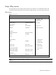
Security menu Figure 17 Security menu ROM-based Setup Utility Main Advanced Boot Exit Install or Change the Security Settings Password. Admin Password: Not Installed User Password: Not Installed Change Admin Password Boot Sector Virus Protection: [Disabled] ←→ Select Screen ↑↓ Select Item Enter Change F1 General Help F10 Save and Exit ESC Exit V02. 61 (C) Copyright 1985-2006, American Megatrends, Inc.
Exit menu The Exit menu displays several options for how to quit the Setup Utility. Select any of the exit options and press Enter. Figure 18 Exit menu ROM-based Setup Utility Main Advanced Boot Security Exit system setup Exit Options after saving the changes. Save Changes and Exit Discard Changes and Exit Discard Changes F10 key can be used for this operation. Restore Default Settings ←→ Select Screen ↑↓ Select Item Enter Go to Sub Screen F1 General Help F10 Save and Exit ESC Exit V02.
Recording custom setup values Write down the settings from the Setup Utility and keep them in a safe place. If the custom values ever need restoring, you must run the Setup Utility and enter these custom settings again. Having a record of these custom settings makes this much easier. Loading system defaults If the system fails after you make changes in the Setup Utility menus, reboot the server, enter Setup, and load the system default settings to correct the error.
ensure that the server is properly functioning. This diagnostic function automatically runs each time the server is powered on. These diagnostics, which reside in the BIOS ROM, isolate the server-related logic failures and indicate the board or component that needs to be replaced, as indicated by the error messages. Most server hardware failures are accurately isolated during POST. The number of tests displayed depends on the configuration of the server.
Table 20 POST Error Messages Error code Description 120 $A0CCMOS Cleared by Jumper. Restore the Jumper and Continue… 122 $A0CPassword Cleared By Jumper.
a. If you have installed an expansion board, verify that the board is firmly seated in its slot and any switches or jumpers on the board are properly set. Refer to the documentation provided with the expansion board. b. All internal cabling and connections are in their proper order. c. If you have changed any jumper block on the system board, verify that each one is properly set. 4. Perform the post-installation procedure described on page . 5. Turn on the monitor. 6.
OS installation Supported OSes Table 21 Supported OSes Option Description Microsoft Windows Microsoft Windows Server 2003 Standard Edition (32/64 bit) Microsoft Windows Server 2003 Enterprise Edition (32/64 bit) Microsoft Windows Server 2003—Web Edition Microsoft Windows Compute Cluster Server 2003 for 64 bit Microsoft Windows Server 2008 Standard Edition (32/64 bit) Microsoft Windows Server 2008 Enterprise Edition (32/64 bit) Microsoft Windows Server 2008 Web Edition Microsoft Windows Server 2008 Small
1. Configure the hardware aspect of the server. 2. Update the server BIOS. Hardware setup Prepare the server following the instructions in the HP ProLiant DL160se G6 Server Installation Sheet. It is recommended that you do not install any third party adapter until you verify that the HP equipment is functioning properly and you complete the OS installation. Your HP ProLiant DL160se G6 server comes with new hard disk drive(s) that do not need specific setup.
Server management Pre- and post-installation procedures Pre-installation procedures WARNING: Failure to properly turn off the server before you open the server or before you start removing or installing hardware components may cause serious damage as well as bodily harm. WARNING: To reduce the risk of personal injury from hot surfaces, allow the chassis and any installed hardware components to cool before touching them.
Post-installation procedures 1. Be sure all components are installed according to the described step-by-step instructions. 2. Check to make sure you have not left loose tools or parts inside the server. 3. Reinstall any expansion boards, riser board assemblies, peripherals, board covers, brackets, and system cables that you have removed. 4. Reinstall the top cover: a. Align the top cover to the chassis and then slide it towards the front panel to position it into place. b.
Index 1 D N 1st Boot Device, 31 Demand Scrubbing, 13 NIC#1 MAC Address, 7 1st Drive, 32 Discard Changes, 34 NIC#2 MAC Address, 7 2 Discard Changes and Exit, 34 Num Lock, 29 2nd Boot Device, 31 E P A Embedded NIC Port 1 Control, 20 Patrol Scrubbing, 13 Embedded NIC Port 2 Control, 20 PCI Configuration, 9 Active Processor Cores, 11 Embedded NIC Port 2 PXE, 21 PCI Express Configuration, 9 Active State Power Management, 22 Embedded NIC Port 1 PXE, 20 POST, 4, 35 Embedded Serial Port Ad
Setup, 4 System Serial Number, 7 USB Configuration, 18 software, 4 System Time, 7 USB Configuration, 9 Standard Boot Order, 27 system time and date setting, 4 USB Device Boot Priority, 27 Status of BMC, 23 T USB Devices Enabled, 18 Subnet Mask, 42 SuperIO Configuration, 9 System BIOS overview, 4 system configuration changing, 4 System Date, 7 system defaults, 35 System Memory, 7 Third IDE Master, 15 User Password Is, 33 TPM Status, 26 W Trusted Computing, 9 Wake-On LAN, 21 U Watch Dog Co