HP ProLiant DL160 Generation 5 Server Software Configuration Guide Part number 449872-001 First edition November 2007
Legal notices © Copyright 2007 Hewlett-Packard Development Company, L.P. The information contained herein is subject to change without notice. The only warranties for HP products and services are set forth in the express warranty statements accompanying such products and services. Nothing herein should be construed as constituting an additional warranty. HP shall not be liable for technical or editorial errors or omissions contained herein. Microsoft, Windows, and Windows NT are U.S.
Contents System BIOS configuration ...................................................................................................................... 5 System BIOS overview .............................................................................................................................. 5 AMIBIOS software ................................................................................................................................... 5 AMIBIOS Setup Utility.................................
Contents 4
System BIOS configuration This chapter describes the basic functions of the AMIBIOS software. System BIOS overview A Basic Input/Output System, or BIOS, is a set of programs permanently stored in an EEPROM chipset (U70) located on the system board. These programs serve as an interface between the server’s hardware components and its operating system.
• When a configuration error is detected by the system and you are prompted by a "Run Setup" message to make changes to the BIOS settings. NOTE: If you repeatedly receive “Run Setup” messages, the battery located on the system board (XBAT1) may be defective. In this case, the system cannot retain configuration values in CMOS. Ask a qualified technician for assistance. The Setup Utility loads the configuration values in a battery-backed nonvolatile memory called CMOS RAM.
Navigating through the Setup Utility Use the keys listed in the legend bar on the bottom of the Setup screen to access the various menu and submenu screens of the Setup Utility. Figure 1in the previous section shows the legend bar at the bottom of the Main menu. Table 1 lists these legend keys and their respective functions. Table 1 Setup Utility navigation keys Key Function ← and → Move between selections on the menu bar. ↑ and ↓ Move the cursor to the field you want.
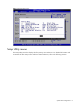
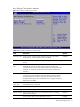
Figure 2 General Help Screen Setup Utility menus The Setup Utility menu bar displays the five primary menu selections. For detailed information and screenshots of these Setup menus and their related submenus, refer to the following sections.
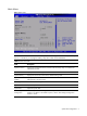
Main Menu Figure 3 Main Menu NOTE: The time is in 24-hour format. For example, 5:30 A.M. appears as 05:30:00, and 5:30, P.M. as 17:30:00. If you unplug the battery, setup time values will be 00:00:00. Table 2 Main menu fields Field Description System Overview Displays the system ROM Version, the date when the Setup utility was created and identification number. Processor Displays the CPU version, speed and count. System Memory Displays the amount of system memory detected during POST.
Boot Settings Configuration submenu Figure 4 Boot Settings Configuration submenu Table 3 Boot Settings Configuration submenu fields Field Description Options Summary Screen Set this value to not allow display hardware summary screen before booting the OS. The setting default value is Disabled. Set this value to allow display hardware summary screen before booting the OS.
Table 3 Boot Settings Configuration submenu fields Field Description Options Set this value. Do not wait for F1. Continue booting. Disabled Advanced menu Figure 5 Advanced menu NOTE: The CPU Configuration setup screen varies depending on the installed processor. Table 4 Advanced menu fields Field Description CPU Configuration You can use this screen to select options for the CPU Configuration Settings. Use the up and down keys to select an item.
Table 4 Advanced menu fields Field Description ACPI Configuration Use this screen to select options for the ACPI Configuration settings. IPMI Configuration Select this option and press to access the submenu. You can use the submenu to view the contents of IPMI .A delay may be noticed when selecting IPMI. This is due to the retrieval of sensor data .In the submenu, use the up and down keys to select an item. Use the and keys to change the value of the selected option.
CPU Configuration submenu Figure 6 CPU Configuration submenu Table 5 CPU Configuration submenu fields Field Description Options C1E Support This should be enabled in order to enable or disable the “Enhanced Halt State.” The setting default value is Enabled. Enabled Disables the item. Adjacent cache line Prefetch debug function is not supported. Disabled A VMM can utilize the additional HW Caps provided by Intel® Virtualization Tech. Enabled The setting default value is Disabled.
IDE Configuration submenu Figure 7 IDE Configuration submenu Table 6 IDE Configuration submenu fields Field Description Options ATA/IDE Configuration Set this value to support compatible mode. The setting default value is Enhanced. Enhanced Set this value to prevent the computer system from using IDE and SATA Device. Disabled Set this mode to support compatible mode. Compatible Set this value to configure SATA as IDE mode. The setting default value is IDE.
Table 6 IDE Configuration submenu fields Field Description Options Hard Disk Write Protect Set this value to allow the hard disk drive to be used normally. Read, write, and erase functions can be performed to the hard disk drive. This is the default setting. Disabled Set this value to prevent the hard disk drive from being erased. Enabled This value is the best setting to use if the onboard IDE controllers are set to a specific IDE disk drive in the BIOS.
IO Device Configuration submenu Figure 8 IO Device Configuration submenu Table 7 IO Device Configuration submenu fields Option Description Disabled Set this value to prevent the serial port from accessing any system resources. When this option is set to Disabled, the serial port physically becomes unavailable. 3F8/IRQ4 Set this value to allow the serial port to use 3F8 as its I/O port address and IRQ 4 for the interrupt address. This is the default setting.
IPMI Configuration submenu Figure 9 IPMI Configuration submenu Table 8 IPMI Device Configuration submenu fields Field Description SEL Configuration Select SEL Configuration in the left frame of the screen to go to the submenu for that item. Then you can press Enter to enter its submenu. You can display a submenu about SEL Configuration option by highlighting it using the keys.
Figure 10 SEL Configuration submenu Table 9 SEL Configuration submenu fields Field Description View BMC System Event Log The option specifies BMC system event log. Select this option and press to access the submenu to view the contents of System Event log. Clear BMC System Event Log The option specifies clear system event log. If the BMC Event log is full, you can choose this item to clear out the BMC Event log.
Figure 11 Serial Port Configuration submenu Table 10 Serial Port Configuration submenu fields Field Description Options Serial Port Assignment This setting will assign the serial port connector to the system. The setting default value is System. System This setting will assign the serial port connector to the BMC (Baseboard management controller). BMC Serial Port Switching This setting allows the Serial port switch between system and BMC. The setting default value is Enabled.
Figure 12 LAN Configuration submenu Table 11 LAN Configuration submenu fields Field Description Options Share NIC Mode Setting this value will prevent support from share NIC mode. The setting default value is Disabled. Disabled Setting this value will allow support share NIC mode (Disabled the KVM). Enabled Setting this value will allow manual IP assignment. Disabled Setting this value will allow dynamic IP assignment. The setting default value is Enabled.
Figure 13 Watchdog Configuration submenu Table 12 Watchdog Configuration submenu fields Field Description Options POST Watchdog Timer Action Set this value to allow BMC to reset if the operating system crashes or hangs. The setting default value is Reset System. Reset System Disabling this option disables any BMC action if OS crashes or hangs. Disabled Set this value to allow BMC to power down if the operating system crashes or hangs.
Figure 14 Hardware health information submenu System BIOS configuration 22
Remote Access Configuration submenu Figure 15 Remote Access Configuration submenu Table 13 Remote Access Configuration submenu fields Field Description Options Remote Access Enable to select Remote Access type. Enabled Disable to select Remote Access type. The setting default value is Disabled.
USB Configuration submenu Figure 16 USB Configuration submenu NOTE: When you install USB storage, USB Mass Device Configuration items are displayed. From this item, you can get some information about the device, some information you can configure it if needed. Table 14 USB Configuration submenu fields Field Description Options USB Controller This setting allows the use of the USB function. The setting default value is Enabled. Enabled This setting makes the onboard USB function unavailable.
Boot Menu Figure 17 Boot Menu Table 15 Boot Menu fields Field Description Boot Device Priority Use this screen to specify the order in which the system checks for the device to boot from. To access this screen, select Boot Device priority on the Boot setup screen and press . The Boot Device Priority screen is displayed. Hard Disk Drives Use this screen to view the hard disk drives in the system. To access this screen, select Hard Disk Drives on the Boot Setup screen and press .
Boot Device Priority submenu To change the boot order, select a boot category type such as Hard disk drives, Removable media or ATAPI CD ROM devices from the boot menu. For example, if the 1st boot device is set to Hard disk drives, then BIOS will try to boot to hard disk drives first. Figure 18 Boot Device Priority submenu NOTE: When you select a boot category from the boot menu, a list of devices in that category appears.
Hard Disk Drives submenu Figure 19 Hard Disk Drives submenu Security menu The Security menu allows users to set an administrator password. When entered, this password allows the user to access and change all settings in the Setup Utility.
To set an administrator password: 1. Indicates whether a supervisor password has been set, if the password has been installed, installed displays, if not, not installed displays. 2. In the Security menu screen, in the Change Administrator Password field, press Enter. The Enter New Password window displays. Figure 21 Enter New Password 3. Type a new password in the Enter New Password box. The password may consist of up to six alphanumeric characters (A-Z, a-z, 0-9), then press Enter.
Figure 22 Confirm New Password 4. Type the same password in the Confirm New Password box to verify the first entry, and then press Enter. The Password Installed OK is displayed. Press OK to finish. Figure 23 Password installed 5. Press F10 to save the password and close the Setup Utility. Setup automatically changes the administrator Password.
To change the administrator password: 1. In the Security menu screen, in the Change Administrator Password field, press Enter. The Enter New Password displays. Type a new password in the Enter New Password box. 2. Type the same password in the Confirm New Password box to verify the first entry, then press Enter. The Password Installed OK is displayed. Press Enter to finish. To clear the administrator password: 1. In the Security menu screen, in the Change Administrator Password field, press Enter.
To check the administrator password: 1. In the Security menu screen, select Password check, and then press Enter. 2. Select one of the available options and then press Enter. Figure 25 Password Check submenu Table 16 Password Check submenu fields Option Description Setup Set this value need to check password while invoking the set up utility. Always Set this value must check password while invoking setup on each boot.
Exit menu The Exit menu displays several options on how to quit the Setup Utility. Select any of the exit options then press Enter. Figure 26 Exit menu Table 17 Exit menu fields Option Description Save Changes and Exit Save the changes made and exit the Setup Utility Discard Changes and Exit Discard the changes and exit the setup utility Discard Changes Discard the changes in the utility Load Optimal Defaults Loads the default settings for all BIOS setup fields.
BIOS Summary Display screen The BIOS Summary Displays basic and important information about the current server configuration and is necessary for troubleshooting and may be required when asking for technical support. This information includes: • • • • Size of the system Serial port base I/O address Available hard drives and expansion boards PCI information It is recommended that you check this screen during the initial system setup and each time you install, remove, or upgrade accessories.
Recording custom Setup values Write down the settings from the Setup Utility and keep them in a safe place. If the custom values ever need restoring (after clearing CMOS, for example), you must run the Setup Utility and enter these custom settings again. Having a record of these custom settings makes this much easier. Loading system defaults If the system fails after you make changes in the Setup menus, reboot the server, enter Setup, and load the system default settings to correct the error.
Power-On Self-Test (POST) When the server boots up, a series of tests are displayed on the screen. This is referred to as PowerOn Self-Test (POST). POST is a series of diagnostic tests that checks firmware and assemblies to ensure that the server is properly functioning. This diagnostic function automatically runs each time the server is powered on.
3. Check the following conditions: a. If you have installed an expansion board, verify that the board is firmly seated in its slot and any switches or jumpers on the board are properly set. Refer to the documentation provided with the expansion board. b. All internal cabling and connections are in their proper order. c. If you have changed any switches on the system board, verify that each one is properly set. 4. Perform the post-installation procedure. 5. Turn on the monitor. 6.
NOS installation Supported NOS Table 18 Supported network operating systems (NOS) NOS Version On-line information site Microsoft Windows • Microsoft Windows Server 2003— Microsoft World Wide Web: Enterprise, Standard, and Web Editions http://www.microsoft.com Microsoft Product Support Services: • Microsoft Windows Server 2003 R2— http://www.support.microsoft.
Hardware setup Prepare the server following the instructions in the HP ProLiant DL160 Generation 5 Server Installation Sheet. It is recommended that you do not install any third party adapter until you verify that the HP equipment is functioning properly and you complete the NOS installation. Your ProLiant server comes with new hard disk drive(s) that do not need specific setup.
Installation flow 1. Create the driver diskettes using the Support CD. 2. Install the Microsoft Windows NOS. 3. Complete the installation—install the drivers for the chipsets, network, and VGA. 4. Configure the system. 5. Configure the network. 6. Install additional HP accessories. Section 1. Creating the driver diskettes To create the appropriate Windows NOS driver diskette: 1. Insert one blank, formatted 3.5" diskette into the floppy drive. 2.
11. On the next screen, select Format the partition using the NTFS file system, then press Enter. 12. The installer formats and copies files to the hard drive, after which the system reboots and launches the Windows NOS graphic interface. Be sure to remove the Windows NOS CD-ROM before rebooting. 13. You can now customize your installation using the graphical interface. NOTE: The network settings may need to be customized to your environment.
4. Follow the installation wizard for additional configuration. 5. Wait for the system to find the appropriate driver, and then click Next. 6. Click Finish after the LAN driver has loaded. 7. Close all open windows and restart the server to properly initialize the LAN adapter. 8. After restarting Windows, configure the network settings for the LAN card to connect to your network. Verify connectivity. Phase 3 - Installing the embedded video driver 1.
5. Click Start | Programs | Administrative Tools | Event Viewer to make sure that there are no errors in the log. NOTE: The Windows NOS Event Viewer may have recorded network errors because your network is not yet configured. Please disregard these errors. 6. Close the Event Viewer window. Phase 2 - Initializing the hard drive There are two types of hard drive configurations: Dynamic and Basic. You can select the appropriate type by right-clicking on the disk drive icon.
○ Terminal Services Manager To create the client installation diskettes: 1. Double-click Terminal Services Client Creator. 2. Select the appropriate client type for your environment. 3. Click Format disk if needed. 4. Check the number of disks required and label them as Terminal Services for […] Disk [x/y]. 5. Click OK to proceed. 6. Follow the on-screen instructions to create the diskette copies. 7. Click OK at the [y] floppies were created… screen. 8.
○ You may test the link further by doing a ping between two clients. At the same command prompt type: ping other_client_IPaddress You should get four replies from the second client. 6. Copy files back and forth from the clients to the server. To test the network link using Terminal Services: 1. Click Start | Programs | Terminal Services Client | Terminal Services Client on a client you installed Terminal Services on. 2. Select the target server from the Available Servers list displayed on the screen.
18. Review the Summary display, then click Next to continue. The system starts configuring the active directory display. It will take a few minutes to complete. 19. If prompted, insert the Windows NOS CD-ROM, then click OK to continue. The Configuring active directory display shows again. 20. Click Finish to close the Wizard utility. This completes the active directory installation. 21. Click Restart Now to reboot the system. Remove the Windows NOS CD-ROM if it is present. 22.
− Optical media drive − Browser that supports HTML ○ Two or more clients for testing purposes (optional) Red Hat Enterprise Linux 4 installation The procedures in this section apply to all versions of the Red Hat Enterprise Linux 4 supported by your ProLiant server. Refer to Table 18 on page 37 for a list of these NOS versions. NOTE: If the system has more than 4 GB of memory, the Red Hat Enterprise Linux installation requires the pci=nommconf parameter. Section 1.
Additional Language Support Review the Additional Language Support setting and modify if necessary, then click Next to continue. Time Zone Selection Review the Time Zone Selection setting and modify if necessary, then click Next to continue. Set Root Password Enter a root password consisting of at least six alphanumeric characters, then click Next to continue. Package Defaults Review the software selection and modify if necessary, then click Next to continue.
System User 1. Skip the option to create a new user, then click Next to continue. 2. On the Warning dialog box, click Next to continue. Additional CDs Ignore this page. Click Next to continue. Finish Setup The initial setup configuration is complete. Click Next to proceed to the login window. Login Type root and the password you set during the NOS installation, then press Enter.
Review the Time Zone Selection setting and modify if necessary, then click Next to continue. Set Root Password Enter a root password consisting of at least six alphanumeric characters, then click Next to continue. Package Defaults Review the software selection and modify if necessary, then click Next to continue. Package Group Selection Review and modify the selection as necessary, then click Next to continue. If you selected the Custom Later option, pre-determined packages have already been selected.
Ignore this page, then click Forward to continue. Create User 1. Skip the option to create a new user, then click Forward to continue. 2. On the Warning dialog box, click Continue. Additional CDs Ignore this page. Click Next to continue. Finish Setup The initial setup configuration is complete. Click Forward to proceed to the login window. Login Type root and the password you set during the NOS installation, then press Enter.
SUSE Linux Enterprise Server 9 installation Section 1. Installing SUSE Linux Enterprise Server 9 1. Turn on the server and insert the SUSE Linux Enterprise Server 9 (SLES9) CD 1. 2. Reboot the system to the SLES9 CD 1. 3. Select Installation, then press Enter to start the installation. 4. Remove the SLES9 SP2 CD1 and insert the SLES9 CD 2 once prompted. 5. Press Enter to proceed to the customization of your installation. Section 2.
Add a New Local User Follow the prompt to add a new local user account, then click Next to continue. Release Note Review the release notes, then click Next to continue. Hardware Configuration Review the default hardware settings and modify them as necessary, then click Next to continue. Installation Completed Click Finish to proceed to the login window. SUSE Linux Enterprise Server 10 Installation Section 1. Installing SUSE Linux Enterprise Server 10 1.
Set host name and domain name, then click Next to continue. Password for the System Administrator Enter a root password consisting of at least six alphanumeric characters, then click Next to continue. Network Configuration Review the Network Configuration settings and verify that they fit your environment, then click Next to continue. Test Internet Connect Review the Network Configuration settings and verify that they fit your environment, then click Next to continue.
Installation flow 1. Install Sun Solaris 10. Refer to the next section for detailed instructions. 2. Install additional HP accessories. The HP ProLiant DL160 Generation 5 Server Support CD includes the drivers for accessories compatible to your server. Refer to the product manual enclosed with the accessory for the detailed installation procedure and/or to the attached readme.txt file associated with the driver. The readme.txt file can be found on the appropriate driver diskette.
Select the language you prefer for the installation, then press Enter to continue. Welcome The Welcome screen appears. Click Next to proceed with the customization. Network Connectivity Click Non-networked, then click Next to continue. Hostname Enter a hostname for the system, then click Next to continue. Time Zone Click Geographic Continent/Country/Region, then click Next to continue. Continent and Country Select the continent and country of your location, then click Next to continue.
Select System Locale Select the appropriate locale once the installation is complete, then click Next to continue. Select Products Select the Solaris software products you need, then click Next to continue. Additional Products For the initial installation, no additional Solaris software is required. Click Next to continue. Select Solaris Software Group Click Entire Group, then click Next to continue. Disk Selection Select a boot disk.
Server management Pre- and post-installation procedures Pre-installation procedures WARNING: Failure to properly turn off the server before you open the server or before you start removing or installing hardware components may cause serious damage as well as bodily harm. WARNING: To reduce the risk of personal injury from hot surfaces, allow the chassis and any installed hardware components to cool before touching them.
(such as a laptop) that is connected to the serial port on the server. The serial port can be controlled by the server or shared between the server and the BMC (the default setting). To configure the BMC through the Setup Utility: 1. In the Serial Port Configuration submenu under the IPMI Configuration submenu, set the Serial port Assignment field to System or BMC. See the “Serial Port Configuration submenu fields” section for more information. 2.
14. Browse the server settings using the user interface that displays. To enable console redirection via the Setup Utility: 1. In the Serial Port Configuration submenu under the IPMI Configuration submenu, set the Serial port Assignment field to System or BMC. See the “Serial Port Configuration submenu fields” section for more information. 2. In the Console Redirection submenu, set Remote Access to Enable. See the “Console Redirection submenu fields” section for more information. 3.
Index A Discard Changes and Exit, 32 administrator password, 27 E administrator password changing, 30 Embedded NIC PXE, 25 administrator password checking, 31 Exit menu, 32 administrator password clearing, 30 F Advanced menu, 11 AMIBIOS Setup Utility, 5 asset tag, 9 ATA/IDE Configuration, 14 B base I/O address, 33 Fan Control Policy, 17 G General Help Screen, 8 H Hard Disk Drives submenu, 27 Baseboard management controller, 19 I Basic Input/Output System, 5 IDE, 16 BIOS EHCI Hand-Off, 24
R Sun Solaris 10, 54 RAID, 16 Sun Solaris 10, installing, 53 Red Hat Enterprise Linux 4, 47, 49 SUSE Linux Enterprise Server NOS, installing, 50 Red Hat Enterprise Linux NOS, installing, 45 SW6, 34 Remote Access, 23 system configuration changing, 5 Remote Access Configuration submenu, 23 System Date, 9 ROM Version, 9 system defaults, 34 S System Time, 9 Save Changes and Exit, 32 system time and date setting, 5 Security menu, 27 U SEL Configuration, 17 USB 2.