
ProLiant DL145 Generation 3 Server Maintenance and Service Guide


Connectors, buttons, and LEDs 68
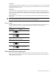
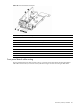
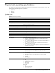
Figure 77 Front panel LED indicators
Item Icon Component Status Description
Blue A UID button has been pressed to toggle the indicator on. 1 UID LED indicator
Off A UID button has been pressed to toggle the indicator off.
Off System health is normal. 2 System health LED indicator
Solid amber A system threshold has been breached. This may be any
of the following:
• At least one fan failure has occurred.
• A voltage regulator error has occurred.
• At least one temperature sensor has reached the
critical level.
• A power supply unit error has occurred.
Solid green An active network link exists.
Flashing
green
An active network link and ongoing network data activity
exist.
3 Activity LED indicators for NIC
1 and NIC 2
Off No network link or network data activity exists.
Flashing
green
Ongoing drive activity (non-hot-plug SATA drives only) 4 HDD activity LED indicator
Off No drive activity exists.
Green The server has AC power and is powered on.
Amber The server has AC power and is in standby mode.
5 Power status LED indicator
(recessed underneath the power
button)
Off The server is powered off (AC power disconnected).
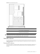
Rear panel LED indicators
The status LED indicators located on the rear panel help monitor network activity and unit identification. Figure
78 shows and describes the function of these LEDs.
Figure 78 Rear panel LED indicators
Item Component Status Description
Blue A UID button has been pressed to toggle the indicator on. 1 UID LED indicator
Off A UID button has been pressed to toggle the indicator off.
Solid green A valid network link exists. 2 Link status LED
indicator for the
10/100 Mbps LAN
port
Off No network link detected.
Flashing amber Network data activity was detected within the preceding one second. 3 Activity status LED
indicator for the
10/100 Mbps LAN
port
Off No network data activity was detected within the preceding one second.
4 NIC link status LED Solid green A valid network link exists.