
ProLiant DL145 Generation 3 Server Maintenance and Service Guide


Connectors, buttons, and LEDs 66
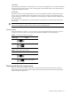
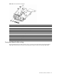
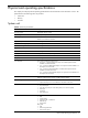
Figure 75 Front panel board components
Item Component code Component
1 J1 Power connector
2 J2 6-pin connector for USB 2.0 ports
3 Riser board with USB 2.0 ports
4 Power status button and LED indicator
5 HDD activity LED indicator
6 Activity LED indicator for NIC 1
7 Activity LED indicator for NIC 2
8 System health LED indicator
9 UID button and LED indicator
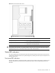
Front panel board cable routing
The front panel board power cable connects to the J11 connector on the system board; the front panel board
USB cable connects to the J13 connector on the system board. Figure 76 shows the routing for both cables.