
ProLiant DL145 Generation 3 Server Maintenance and Service Guide


Connectors, buttons, and LEDs 64
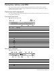
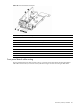
Item Component code Component
1 — Broadcom BCM5715 dual gigabit Ethernet controller
2 J3 GbE LAN ports for NIC 1 and NIC 2
3 J5 USB 2.0 ports and 10/100 Mbps LAN port for IPMI management
4 J4 PS/2 keyboard and mouse ports
5 J2 Serial port
6 — Server Engines Pilot service management controller (SMC) chip
7 J1 Video port
8 SW3 NMI button (recessed)
9 SW1 UID button and separate LED indicator (blue)
10 — Broadcom BCM5785 HyperTransport-connected system I/O hub and PCI-X bridge
11 J7 IDE data cable connector
12 J10 64-bit/133 MHz PCI-X slot
13 J11 26-pin front panel board power connector
14 J12 Debug port
15 J13 6-pin connector for the front USB 2.0 ports
16 U70 BIOS flash Electrically Erasable Programmable Read-Only Memory (EEPROM)
17 P22 14-pin system board power connector
18 P56 3-pin crisis recovery setting jumper block
19 P57 3-pin CMOS setting jumper block
20 J15 PCI Express x4 slot
21 DIMM5 to DIMM8
(left to right)
Processor 2 socket (U55) DIMM slots
22 P19 7-pin 150-MBps SATA 1 connector
23 P23 7-pin 150-MBps SATA 2 connector
24 P47, P48, and P49
(left to right)
4-pin system fan connectors
25 U55 AMD Opteron 1207-pin processor 2 socket
26 DIMM1 to DIMM4
(left to right)
Processor 1 socket (U42) DIMM slots
27 XBAT1 3 V internal lithium system battery
28 P41 4-pin hard drive/optical drive power cable connector
29 P34 22-pin system board power connector
30 U49 Broadcom BCM2100 HyperTransport tunnel and PCI Express bridge
31 U42 AMD Opteron 1207-pin processor 1 socket
32 J14 PCI Express x16 slot
33 J6 and J9 1 GHz, 16x16 HTX slot
34 — Mounting Holes
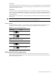
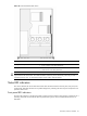
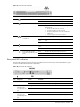
System buttons
The system board contains the rear UID button (SW1) and the NMI button (SW3). Both are accessible from the
rear panel; the NMI button is recessed. Figure 73 on page 62 shows the locations of both buttons on the rear
panel; Figure 74 on page 63 shows the locations on the system board.
The front panel board contains the front UID button, which is accessible from the front panel. Figure 72 on page
62 shows the location of the UID button on the front panel; Figure 75 on page 66 shows the locations on the
front panel board.