
ProLiant DL145 Generation 3 Server Maintenance and Service Guide

Removal and replacement procedures 42
NOTE: You cannot install the PCI Express x4 and PCI-X riser boards at the same time. You also cannot install
the HTX and PCI Express x16 riser boards at the same time.
Expansion board installation guidelines
Use only HP-supported expansion boards that meet the following specifications:
• HTX: Full-sized, 1 GHz, 16x16
• PCI Express x4: Low-profile
• PCI Express x16: Full-sized
• PCI-X: Low-profile, 64-bit, 3.3 V, 133 MHz
For ease of reading, the riser board assembly will be referred to as the “assembly” in the following sections.
Also, in some figures, the plane section of the assembly is dimmed out for clarity.
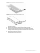
Removing a riser board assembly
1. Perform the pre-installation procedures described on page 11.
2. Locate the assembly you want to remove:
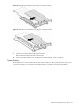
• To install, remove, or replace an HTX or PCI Express x16 expansion board or riser board, remove the
full-sized assembly.
• To install, remove, or replace a PCI-X or PCI Express x4 expansion board or riser board, remove the
low-profile assembly.
3. If an expansion board is installed in the assembly, disconnect any cables that connect the expansion board
to the system board.
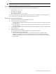
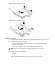
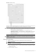
4. Remove the appropriate assembly:
a. Loosen the two captive thumbscrews that secure the assembly to the chassis.
b. Lift the assembly away from the chassis.
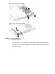
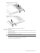
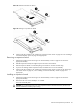
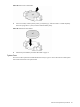
If you are removing the full-sized assembly, first lift the assembly from the end with the captive
thumbscrews to disconnect the riser board from the expansion slot on the system board. Slide the
assembly approximately 1.25 cm (0.5 in) toward the rear of the chassis, then lift the assembly away
from the chassis.