
ProLiant DL145 Generation 3 Server Maintenance and Service Guide
Removal and replacement procedures 28
8. Perform the post-installation procedures described on page 12.
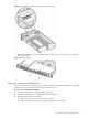
Installing a hot-plug SATA/SAS controller board
To enable hot-plug SATA/SAS drive functionality, you must install the hot-plug SATA/SAS backplane in addition
to a hot-plug SATA/SAS controller board and cabling. This procedure assumes the backplane is already
installed. See the “Installing the hot-plug SATA/SAS backplane” section described on page 26 for more details.
To install a hot-plug SATA/SAS controller board:
1. Perform the procedure in the “Removing a riser board assembly” section on page 42 to remove the
appropriate riser board assembly.
If the hot-plug controller board you want to install is a PCI-X or PCI Express x4 board, remove the low-
profile assembly. If the hot-plug controller board you want to install is a PCI Express x16 board, remove the
full-sized assembly.
2. Prepare the assembly:
• If no riser board is installed in the assembly, perform the procedure in the “Installing a riser board”
section on page 45 to install the correct riser board for the controller board you want to install.
• If the riser board installed in the assembly is not the correct type, perform the procedures in the
“Removing a riser board” section on page 43 and the “Installing a riser board” section on page 45 to
replace the riser board.
• If the correct riser board is installed in the assembly but an expansion board is installed, perform the
procedure in the “Removing an expansion board” section on page 46.
• If the correct riser board is installed in the assembly and no expansion board is installed, continue to
the next step.
3. Perform steps 2 to 6 in the “Installing an expansion board” section described on page 46 to install the hot-
plug controller board in the assembly.
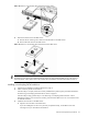
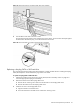
4. Connect the wide connector on one end of the hot-plug SATA/SAS cable assembly to the data connector
on the hot-plug controller board.
5. Perform step 1 of the “Installing a riser board assembly” section on page 43 to reinstall the assembly in the
server.
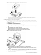
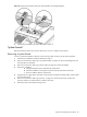
6. For a low-profile controller board, route the hot-plug SATA/SAS cable assembly as follows:
a. From the controller board, route the cable assembly between the processor 2 socket DIMM slots and
the PCI Express x4 slot to the right edge of the chassis (as viewed from the front of the server).
b. Route the cable assembly toward the front of the chassis, following the bundled cables.
c. Route the cable assembly between the drive bays and the system fans.
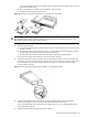
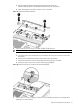
7. For a full-sized controller board, route the hot-plug SATA/SAS cable assembly as follows:
a. From the controller board, route the cable assembly toward the front of the server between the power
supply and the system fan closest to the power supply.
b. Route the cable assembly between the drive bays and the system fans.
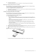
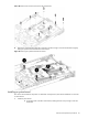
8. Connect the hot-plug SATA/SAS cable assembly to the hot-plug backplane:
a. Connect the longer SATA/SAS data cable to the data connector on the backplane farthest from the
controller board.
b. Connect the LED cable to the connector on the backplane beneath the HDD bay 1 data connector.
c. Connect the shorter SATA/SAS data cable to the data connector on the backplane closest to the
controller board.