
ProLiant DL145 Generation 3 Server Maintenance and Service Guide

Removal and replacement procedures 27
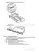
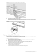
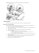
a. Align the hot-plug backplane between the drive bays and the system fans.
The data cable connectors on the backplane should face the rear of the chassis.
b. Attach the backplane to the chassis with the screws on each end.
Figure 25 Installing the hot-plug backplane
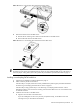
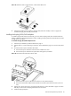
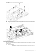
6. Connect and route the new drive power cable included with the option kit:
NOTE: Do not reuse the power cable you removed in step 3.
a. Connect the square 4-pin end of the drive power cable to the drive power connector on the system
board (P41).
b. Route the power cable between the drive bays and the system fan locations.
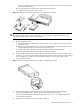
c. Connect the small power connector to the optical drive docking board, if installed.
d. Connect the square 4-pin power connector to the hot-plug backplane.
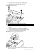
Figure 26 Connecting the power connector to the hot-plug backplane
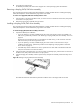
7. Perform steps 1 to 3 in the “Installing a system fan” section described on page 53 to reinstall the three
system fans you removed earlier.