
ProLiant DL145 Generation 3 Server Maintenance and Service Guide

Removal and replacement procedures 18
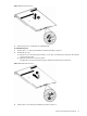
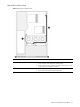
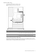
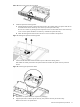
Figure 9 Hot-plug SATA/SAS hard drive cable routing with a full-sized controller board
Item Description Connections
1 Hot-plug SATA/SAS backplane power
cable
• P41 on the system board
• Power connectors on the hot-plug SATA/SAS backplane
• Power connector on the optical drive docking board, if installed
2
Hot-plug SATA/SAS cable assembly
• Data connector on the hot-plug SATA/SAS controller board
• Data connectors and the LED connector on the hot-plug SATA/SAS
backplane
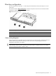
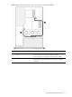
Optical drive
The optical drive bay supports the installation of a 9.5-mm CD-ROM or CD/DVD combo drive. Go to the HP
website at http://www.hp.com/
and refer to the options list for this server model for a list of supported optical
drives.
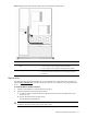
To install a CD-ROM or CD/DVD combo drive:
1. Perform the pre-installation procedures described on page 11.
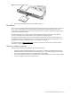
2. Remove the optical drive bay bezel from the chassis:
a. Push down on the two bezel tabs above the optical drive bay on the non-removable section of the
chassis top cover.
b. Remove the bezel from the optical drive bay.
Store the bezel for reassembly later.
CAUTION: Do not discard the bezel. If the optical drive is removed in the future, this bezel must be
reinstalled in the chassis for the proper cooling of the system.