
HP ProLiant DL145 Generation 2 Server Installation Sheet


IMPORTANT: If you removed a hard drive without plans of installing a new
one, you must reinstall the mounting screws at their pre-installed location
for future use, then reinstall the HDD carrier in the chassis for the proper
cooling of the system.
Configuring a SCSI Hard Drive
The steps listed below give an overview of the SCSI hard drive
configuration procedure:
1. Install the SCSI hard drive.
2. Install the SCSI controller board.
Refer to the “Installing a PCI Expansion Board” section for
detailed procedures.
3. Route the SCSI drive cables.
Refer to the SCSI Cable Installation Instructions document that
came with the SCSI cable option kit for detailed procedures.
4. Set up the SCSI configuration.
Refer to the documentation that came with the SCSI controller
board for detailed procedures.
To install a SCSI hard drive:
1. Perform the pre-installation procedures described earlier.
2. Select which drive bay you will use to install the new hard
drive.
If the desired drive bay is occupied, remove the currently
installed drive following the procedures described in the
“Removing a Hard Drive” section.
If the desired drive bay is empty, perform step 3 of the
“Removing a Hard Drive” section, then remove four mounting
screws from the HDD carrier. You will use these screws to
install the new drive.
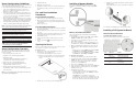
3. Install the new SCSI hard drive in its carrier:
If you are installing the new drive in a previously occupied
drive bay, use the HDD carrier and mounting screws you
removed from the old drive.
If you are installing the new drive in an empty drive bay, use
the HDD carrier and mounting screws you removed from that
drive bay.
a. Align the new hard drive on the carrier.
b. Secure the hard drive assembly with the four mounting
screws.
c. Slide the hard drive assembly into the chassis.
Configuring a SATA Hard Drive
Configuring a SATA hard drive is a two-step process that includes:
1. Install the SATA hard drive.
2. Set up the SATA configuration.
For detailed procedures, refer to the Server Support CD or to
the operating system documentation.
To install a SATA hard drive:
1. Install the SATA hard drive by following the steps described in
the “To install a SCSI hard drive” section.
CAUTION: Route the SATA drive cables neatly. If necessary,
secure them using the pre-installed cable clips located on the
chassis base. The cables should be routed in a position where they
will not be pinched or crimped by the top cover, nor should they
hamper proper airflow inside the chassis.
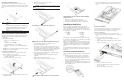
2. Route the SATA drive cables:
a. Route the SATA and power cables through the cable
management opening of the chassis’ partition wall.
b. Connect the SATA and power cables to their corresponding
connectors on the rear of the new drive.
c. Check that all cables are clear of the hard drive carrier and
are properly routed to their corresponding connectors, then
tighten the screw that secures the hard drive assembly to the
chassis.
3. Perform the post-installation procedures described earlier.
Installing an Optional CD-ROM or
DVD Drive
The optical media device bay supports the installation of a
slim-type CD-ROM or DVD-ROM drive. Go to the HP website at
http://www.hp.com/ and refer to the options list for this server model
for a list of supported optical media drives.
To install an optional CD-ROM or DVD drive:
1. Perform the pre-installation procedures described earlier.
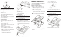
2. Prepare the optical media device bay for installation:
a. Pull up the optical media device bay release lever, then
push the drive carrier partially out through the front of the
chassis.
b. Pull the drive carrier out of the chassis.
c. Remove the screw securing the drive carrier bezel.
d. Detach the drive carrier bezel.
Store the drive carrier bezel (with its screw) for reassembly
later.
CAUTION: Do not discard the drive carrier bezel. If the optical drive
is removed in the future, this bezel must be reinstalled in the
chassis for the proper cooling of the system.
3. Remove the new optical drive from its protective packaging.
The optical drive option kits include mounting screws for drive
installation.
4. Install the new optical drive in its carrier:
a. Align the optical drive in the carrier.
b. Secure the drive with two mounting screws.
5. Install the new optical drive into the chassis:
a. Slide the drive assembly into the chassis until the optical
media device bay release lever snaps into place.
CAUTION: Route the optical drive cables neatly. If necessary,
secure them using the pre-installed cable clips located on the
chassis base. The cables should be routed in a position where they
will not be pinched or crimped by the top cover, nor should they
hamper proper airflow inside the chassis.
b. Route the optical drive’s power cables through the cable
management opening of the chassis’ partition wall.
c. Connect the IDE data and power cables to their
corresponding connectors on the optical drive’s backplane
board.
6. Perform the post-installation procedures described earlier.