
HP ProLiant DL145 Generation 2 Server Installation Sheet

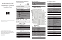


PCI Riser Board Expansion Slots
The two PCI-X riser boards attached to the PCI riser board
assembly convert the functionality of the system board expansion
slots to a pair of slots positioned at a 90° angle from the system
board.
Item Component
1 Standard height/full-length 64-bit/133 MHz PCI-X riser
board
Users have the option to replace this riser board with a PCI
Express model using the PCI Express riser board option kit.
This will allow support for PCI Express x16 expansion
boards.
2 Low profile 64-bit/133 MHz PCI-X riser board
Expansion Board Installation Guidelines
The system supports up to two expansion boards at a time. Use
only HP supported expansion boards that meet the following
specifications:
• PCI or PCI-X compliant
— Connector: 32 or 64 bits wide, 3.3 V
— Speed
PCI board speed: 66 MHz
PCI-X board speed: 100 or 133 MHz
— Form factor: low profile or standard height/full-length
boards
• PCI Express x16 compliant (available only when the optional
PCI Express riser board is installed)
To install a PCI expansion board:
1. Perform the pre-installation procedures described earlier.
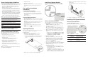
2. Remove the
PCI riser board assembly:
a. Loosen the two captive thumbscrews that secure the
assembly to the chassis.
b. Lift the assembly away from the chassis.
3. Identify the slot that is compatible with the expansion board
you intend to install.
4. Pull out the slot cover from the selected slot.
Store it for reassembly later.
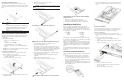
CAUTION: Do not discard the slot cover. If the expansion board is
removed in the future, the slot cover must be reinstalled to
maintain proper cooling.
Removing the cover of the low–profile expansion slot
Removing the cover of the standard height/full-length expansion
slot
5. Remove the PCI expansion board from its protective
packaging, handling it by the edges.
Some expansion boards can only be installed in one slot but
other boards can be configured to fit in either slot by replacing
the default bracket (attached to the board) with a different sized
one. The different sized bracket and instructions on how to
attach it to the board is included in the option kit.
6. Verify that the board’s default bracket is compatible with the
configuration of the selected slot.
If it is not compatible, replace the bracket with one that is
compatible.
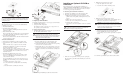
7. Slide the expansion board into the slot.
Firmly press the board to seat it properly on the slot.
Installing the SCSI controller board in the low–profile expansion
slot
Installing the SCSI controller board in the standard height/full-
length expansion slot
8. Connect the necessary cable(s) to the board.
Refer to the documentation that came with the board.
9. Perform the post-installation procedures described earlier.
Installing a Hard Drive
The server’s two 1-inch hard disk drive bays support both
non-hot-plug SCSI and SATA drives. The default system comes
with a single hard drive, the type and capacity of which varies
based on the server model. The ProLiant server currently supports
the following drive capacities:
• SCSI HDD
— 36 GB
— 72 GB
• SATA HDD
— 80 GB
— 160 GB
— 250 GB
The SCSI drive and the 80 GB SATA drive options include only
the hard disk. Use the HDD carriers and mounting screws included
with your server to install these drives.
The 160- and 250-GB SATA drive options come with a hot-plug
HDD carrier. You need to remove the drives from their default
carriers before installing them in the server. Use the HDD carriers
and mounting screws included with your server to install these
drives.
Go to the HP website at
http://www.hp.com/ and refer to the options
list for this server model for the latest information on supported
hard drives.
Hard Drive Installation Guidelines
Observe the following important guidelines when installing hard
drives:
• Install only hard drive models specified for your ProLiant
server. Installing unsupported hard drives may damage the
system by consuming power and generating heat in excess of
the server’s operating tolerance. This condition may result in a
loss of system and/or data integrity.
• Install hard disks in the drive carriers included with the server
chassis using four of the six HDD screws pre-installed in each
of the two HDD carriers.
• Hard drives installed in the server are labeled as Device 0 and
Device 1 from left to right when viewed from the front of the
server.
Removing a Hard Drive
If you intend to install a new hard drive in an occupied drive bay,
remove the old drive first. Use the drive carrier and screws you
removed from the old drive to install the new hard drive.
To remove a hard drive:
1. Perform the pre-installation procedures described earlier.
2. Disconnect the data and power cables from the rear of the hard
drive.
3. Remove the hard drive from the chassis:
a. Loosen the screw that secures the HDD carrier to the
chassis.
b. Push the HDD carrier towards the front of the chassis, then
slide it out completely.
4. Remove the hard drive from its carrier:
a. Remove the four mounting screws that secure the hard
drive to the carrier.
b. Remove the hard drive from its carrier.