
HP ProLiant DL145 Generation 2 Server Installation Sheet


Server Configuration Guidelines
Observe the following important guidelines before performing any
of the configuration steps listed in the next section.
• For safety information and detailed procedures related to step 3
of the “Server Configuration Overview” section, refer to
Chapter 2 of the HP ProLiant DL145 Generation 2 Server
Maintenance and Service Guide.
• For safety information and detailed procedures related to the
rest of the steps listed in the “Server Configuration Overview”
section, refer to relevant chapter on the HP ProLiant DL145
Generation 2 Server User Guide.
• Refer to the HP ProLiant DL145 Generation 2 Server Support
CD for additional information and updates not provided in this
installation sheet. You can also access additional information
and documentation from the HP website at
http://www.hp.com/,
either by connecting directly or through the Support CD.
NOTE: The procedures described in this installation sheet assume that the
server is out of the rack and is positioned on a flat, stable surface.
IMPORTANT: Observe the pre- and post-installation procedures described
in later sections when performing any configuration procedure.
CAUTION: Follow the ESD precautions listed in Chapter 2 of the
HP ProLiant DL145 Generation 2 Server Maintenance and Service
Guide when handling any hardware component.
WARNING: Failure to properly turn off the server before you
open the server or before you start removing/installing hardware
components may cause serious damage as well as bodily harm.
WARNING: To reduce the risk of personal injury from hot
surfaces, allow the chassis and any installed hardware
component to cool before touching them.
Server Configuration Overview
The steps listed below give an overview of the necessary setup
procedures for preparing the HP ProLiant DL145 Generation 2
server for operation.
1. Select an appropriate site for the server.
2. Unpack the server and rack-mounting hardware.
3. Install other options.
Other options include additional memory, hard drives,
expansion boards, and external storage devices.
4. Connect the power cord and peripheral devices.
5. Turn on the server and determine the BIOS version.
Update the BIOS version if necessary.
6. Install a supported operating system of your choice.
For detailed procedures, refer to the documentation provided
by the OS vendor.
NOTE: For a list of operating systems supported by your ProLiant server,
go to
http://www.hp.com/go/supportos.
7. Install the rack rails.
8. Mount the server in the rack.
9. Configure the settings for the server’s management functions.
For detailed procedures, refer to the Lights-Out 100i User
Guide.
Pre- and Post-Installation
Procedures
Pre-installation Procedures
1. Turn off the server and all the peripherals connected to it.
2. Disconnect the AC power cord from the power supply cable
socket located on the server rear panel to eliminate the risk of
electrical shock.
3. Remove the top cover.
Post-installation Procedures
1. Be sure all components are installed according to the described
step-by-step instructions.
2. Check to make sure you have not left loose tools or parts inside
the server.
3. Reinstall any expansion board(s), peripheral(s), board cover(s),
and system cable(s) that have previously been removed.
4. Reinstall the top cover.
5. Connect all external cables and the AC power cord to the
system.
6. Press the power button
on the front panel to turn on the
server.
Opening the Server
The top cover is detachable. You need to remove this cover before
you can remove or replace a server component.
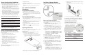
To open the server:
1. Perform steps 1 and 2 of the pre-installation procedures.
2. Detach the top cover from the chassis:
a. Loosen the captive thumbscrew on the rear panel.
b. Slide the cover approximately 1.25 cm (0.5 in) toward the
rear of the unit, then lift the cover to detach it from the
chassis.
3. Place the top cover in a safe place for reinstallation later.
Installing a Memory Module
The system has eight DIMM slots that support up to 16 GB
maximum system memory (2 GB in each of the eight DIMM
slots).
Memory Installation Guidelines
Observe the following important guidelines when installing
memory modules:
• Use only HP supported PC3200 (400 MHz) registered ECC
DIMMs in 512 MB, 1 GB, or 2 GB capacities
• In a single processor configuration, the processor 1 socket
(U22) must be populated.
• The processor 2 socket (U11) must be populated before you
can install memory modules in the DIMM5 to DIMM8 slots.
• Memory modules must be installed in pairs of the same size.
• Install memory modules following the slot sequence listed
below:
— For the processor 1 socket DIMM slots: Populate DIMM3
and DIMM4 first, then DIMM1 and DIMM2.
— For the processor 2 socket DIMM slots: Populate DIMM7
and DIMM8 first, then DIMM5 and DIMM6.
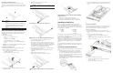
To install a memory module:
1. Perform the pre-installation procedures described earlier.
2. If you intend to install a memory module in the DIMM5 to
DIMM8 slots, lift the air duct away from the chassis first.
3. If necessary, remove any accessory boards or cables that
prevent access to the DIMM slots.
4. Locate an empty DIMM slot on the system board.
5. If necessary, open the holding clips of the selected DIMM slot.
6. Remove the memory module from its protective packaging,
handling it by the edges.
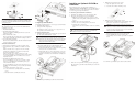
7. Install the memory module:
a. Orient the module so that the notch on its bottom edge
aligns with the keyed surface of the DIMM slot, and then
press it fully into the slot.
The DIMM slots are structured to ensure proper
installation. If you insert a memory module but it does not
fit easily into the slot, you may have inserted it incorrectly.
Reverse the orientation of the module and insert it again.
b. Firmly press the holding clips inward to secure the memory
module in place.
If the holding clips do not close, the module is not inserted
correctly
8. Perform the post-installation procedures described earlier.
Installing a PCI Expansion Board
Server I/O System Overview
System Board PCI Expansion Slots
There are three PCI expansion slots on the system board.
Item Component Function
1 64-bit/133 MHz
PCI-X slot
Supports a low profile 64-bit/
133 MHz PCI-X riser board
2 64-bit/133 MHz
PCI-X slot
Supports a standard height/
full-length 64-bit/ 133 MHz PCI-X
riser board
3 PCI Express x16
slot
Supports a full-length PCI Express
x16 riser board