
HP ProLiant DL140 Generation 3 Server Maintenance and Service Guide

Contents 60
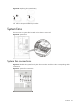
Device number Connector
System fan 1 to 4 CN3 to CN6 on the front
panel board
System fan 5 CN9 on the system board
System fan 6 CN8 on the system board
NOTE: System fans 1 to 5 are for the memory modules
and processors, while system fan 6 is for the PCI slots
and system chipsets.
To replace the system fan:
A new system fan can be installed to allow the server to operate properly in case a default system fan
becomes defective.
1. Perform the pre-installation procedure.
2. Locate the system fan you want to replace.
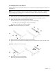
3. Remove the system fan you want to replace.
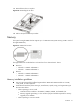
a. Disconnect the fan cable from its corresponding board connector.
If you are replacing system fan 1 – 4, release the fan cable from the cable clips securing it to
the base of the chassis.
If you are replacing system fan 5 or 6, pull the fan cable through the opening in the center
wall
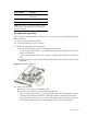
b. Tug the fan cable upward to release the fan from its bracket, and then pull the fan away from
the bracket.
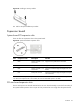
Figure 52 Removing a system fan
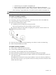
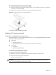
4. Install a new system fan.
a. Insert the new fan into the vacated fan bracket.
b. Connect the fan cable to its corresponding board connector.
If you are replacing system fan 1 – 4, connect the fan cable to the corresponding connector
on the front panel board, and then secure it through its fastener on the base of the chassis.
If you are replacing system fan 5 or 6, route the fan cable through the opening in the center
wall, and then connect them to their corresponding connectors on the system board.