
HP ProLiant DL140 Generation 3 Server Maintenance and Service Guide


Contents 35
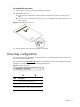
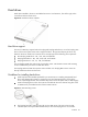
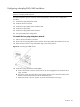
Figure 7 Preparing the optical media device bay for installation
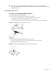
3. Remove the new optical drive from its protective packaging.
The optical drive option kits include mounting screws for drive installation.
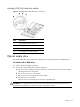
4. Install the new optical drive in its carrier.
a. Align the optical drive in the carrier.
b. Secure the drive with two mounting screws.
Figure 8 Installing the optical media drive in its carrier
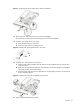
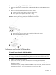
5. Install the new optical drive into the chassis.
a. Slide the optical drive assembly into the chassis until the media device bay release lever
snaps into place.
b. Make sure the optical drive cables are routed neatly. Secure them using the pre-installed
cable clips located on the chassis base.
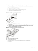
c. Connect the IDE data and power cables to their corresponding connectors on the optical
drive’s backplane board.
Figure 9 Installing the optical drive assembly in the chassis
6. Perform the post-installation procedure.