
SCSI Cable Installation Instructions for HP ProLiant DL100 Series Generation 2 Servers


f. Fold the terminated end of the SCSI cable in the manner
illustrated in the following figure.
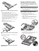
To route the SCSI drive cables when the controller
board is installed in the standard height/full-length
expansion slot:
g. Reattach the mylar sheet over the cable back to the air duct
surface.
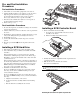
1. Connect the SCSI cable to the SCSI controller board:
h. Route the SCSI cable through the cable management
opening of the chassis’ partition wall.
a. Connect the cable to the corresponding connector on the
SCSI controller board.
b. Fold the connector end of the SCSI cable in the manner
illustrated in the following figure.
c. Attach a tie wrap (included in the SCSI cable option kit) in
the 240 mm location of the cable.
i. Route the power cable through the cable management
opening of the chassis’ partition wall.
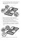
j. Connect the SCSI and power cables to their corresponding
connectors on the rear of the new drive.
Make sure the terminated end of the SCSI cable is
positioned in the manner illustrated in the figure below.
k. Check that all cables are clear of the hard drive carrier and
are properly routed to their corresponding connectors, then
tighten the screw that secures the hard drive assembly to the
chassis.
2. Route the SCSI cable towards the SCSI hard drive:
a. Align the assembly with the retainers on the rear of the
chassis.
b. Tighten the two captive thumbscrews to secure the
assembly to the chassis.
c. Route the SCSI cable between the IDE cable and the power
supply unit making sure it lays flat between this space.
3. Perform the post-installation procedures described earlier.
d. Disconnect the following cables from their system board
connectors— the 8-pin ATX CPU power cable, the 24-pin
ATX system board power cable, and the 4-pin I
2
C PSU
cable.
e. Route the SCSI cable underneath the three cables you
disconnected in the previous step.