
ProLiant DL140 Generation 2 Server Maintenance and Service Guide

Connectors, switches, and LEDs 62
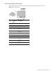
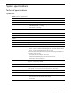
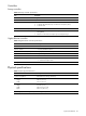
Front panel board cable routing
Figure 68 Front panel board cable routing
Item Connector Cable
1 JP1 Front panel board power cable
Connects to the PSU.
2 CN9 Front panel board system board
cable
Connects to CN12 on the system
board.
3 CN1 to
CN4
4-pin system fan cables
Connects to the system fans 1 to 4.
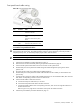
To route the front panel board cables:
CAUTION: Route the front panel board cables neatly. If necessary, secure them using the pre-installed cable
clips located on the chassis base. The cables should be routed in a position where they will not be pinched or
crimped by the top cover, nor should they hamper proper airflow inside the chassis.
NOTE: For ease of reading, front panel board will be simply referred to as “FPB” in the following procedures.
1. Perform the pre-installation procedure described on page 13.
2. Remove the PCI riser board assembly following the procedures described on page 34.
3. Connect the FPB system board cable to the CN12 connector on the system board.
4. Route the FPB power and system board cables through the cable management opening of the chassis’
partition wall.
5. Disconnect the drive and power cables of the available hard drives.
6. Route the FPB power and system board cables underneath the hard drive cables you disconnected in the
previous step.
7. Arrange the drive and power cables of the available hard drives over the routed FPB cables, then reconnect
them to their corresponding connectors on the rear of the drives.
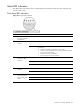
8. Connect the FPB cables to their FBP connectors.
a. Connect the FPB power cable to the JP1 connector.
b. Connect the FPB system board cable to the CN9 connector.
c. Connect the FPB fan cables to their corresponding connectors, then secure it through their fasteners on
the base of the chassis.
Refer to Figure 52 on page 38 for an illustration of the system fan cable connections.
9. Perform the post-installation procedure described on page 13.