
ProLiant DL140 Generation 2 Server Maintenance and Service Guide

Removal and replacement procedures 39
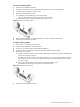
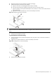
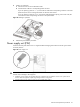
4. Install a new system fan.
a. Insert the new fan into the vacated fan bracket.
b. Connect the fan cable to its corresponding board connector.
If you are replacing system fan 1 – 4, connect the fan cable to the corresponding connector on the front
panel board, then secure it through its fastener on the base of the chassis.
If you are replacing system fan 5 or 6, route the fan cable through the opening in the center wall, then
connect them to their corresponding connectors on the system board.
Figure 54 Installing a system fan
5. Perform the post-installation procedure.
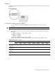
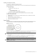
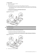
Power supply unit (PSU)
Located on the rear panel of the server is a single standard autoranging 500-watts PSU with PFC (power factor
correction) function.
Figure 55 Power supply unit
WARNING! Take note of the following reminders to reduce the risk of personal injury from electric shock
hazards and/or damage to the equipment.
•
Installation of power supply units should be referred to individuals who are qualified to service server systems and are
trained to deal with equipment capable of generating hazardous energy levels.
• DO NOT open the power supply unit. There are no serviceable parts inside it.