
ProLiant DL140 Generation 2 Server Maintenance and Service Guide

Removal and replacement procedures 35
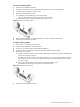
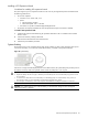
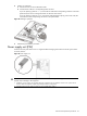
3. Remove the PCI Express riser board from its protective packaging.
4. Install the PCI Express riser board on the assembly.
a. Align the riser board on the full-length bracket side of the assembly.
b. Secure the riser board to the assembly using the three screws you removed in step 2.
c. Align the assembly with the system board expansion slots, then press it down to ensure full connection
to the system board.
d. Tighten the two captive thumbscrews to secure the assembly to the chassis.
Figure 47 Installing the PCI Express riser board
NOTE: When a standard height/full-length expansion board is installed on the PCI Express riser board slot,
make sure that the corner of the expansion board is engaged to the PCI retainer bracket located on the system
board.
5. Perform the post-installation procedure.
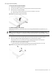
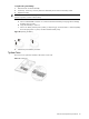
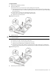
To reinstall the PCI riser board assembly:
1. Align the assembly with the system board expansion slots, then press it down to ensure full connection to
the system board.
2. Tighten the two captive thumbscrews to secure the assembly to the chassis.
Figure 48 Reinstalling the PCI riser board assembly
3. Perform the post-installation procedure.