
ProLiant DL140 Generation 2 Server Maintenance and Service Guide

Removal and replacement procedures 25
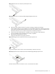
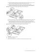
d. Disconnect the following cables from their system board connectors—the 8-pin ATX processor power
cable, the 24-pin ATX system board power cable, and the 4-pin I
2
C PSU cable.
e. Route the SCSI cable underneath the three cables you disconnected in the previous step.
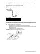
f. Arrange the ATX processor power cable, the ATX system board power cable, and the I
2
C PSU cable
over the routed SCSI cable, then reconnect them to their corresponding system board connectors.
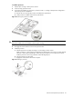
Figure 28 SCSI cable routing for standard height/full-length controller boards phase 3
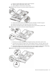
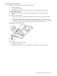
g. Route the SCSI and power cables through the cable management opening of the chassis’ partition wall.
h. Connect the SCSI and power cables to their corresponding connectors on the rear of the new drive.
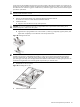
Make sure the terminated end of the SCSI cable is positioned in the manner illustrated Figure 29.
i. Check that all cables are clear of the hard drive carrier and are properly routed to their corresponding
connectors, then tighten the screw that secures the hard drive assembly to the chassis.
Figure 29 SCSI cable routing for standard height/full-length controller boards phase 4
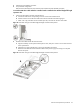
3. Perform the post-installation procedure.
4. Set up the SCSI configuration.
Refer to the documentation that came with the SCSI controller board for detailed procedures.