
ProLiant DL140 Generation 2 Server Maintenance and Service Guide

Removal and replacement procedures 24
3. Perform the post-installation procedure.
4. Set up the SCSI configuration.
Refer to the documentation that came with the SCSI controller board for detailed procedures.
To route the SCSI drive cables when the controller board is installed in the standard height/full-length
expansion slot:
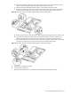
1. Connect the SCSI cable to the SCSI controller board.
a. Connect the cable to the corresponding connector on the SCSI controller board.
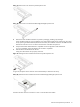
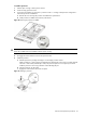
b. Fold the connector end of the SCSI cable in the manner illustrated in the following figure.
c. Attach a tie wrap (included in the SCSI cable option kit) in the 240 mm location of the cable.
Figure 26 SCSI cable routing for standard height/full-length controller boards phase 1
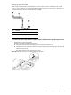
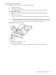
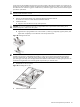
2. Route the SCSI cable towards the SCSI hard drive.
a. Align the assembly with the system board expansion slots, then press it down to ensure full connection
to the system board.
b. Tighten the two captive thumbscrews to secure the assembly to the chassis.
c. Route the SCSI cable between the IDE data cable and the power supply unit making sure it lays flat
between this space.
Figure 27 SCSI cable routing for standard height/full-length controller boards phase 2