
ProLiant DL140 Generation 2 Server Maintenance and Service Guide

Removal and replacement procedures 23
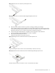
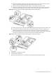
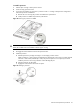
c. Use the two retainer tabs on the air duct to secure the cable.
d. Open the protective mylar sheet on the air duct.
e. Lay the cable flat in the slot on the air duct surface.
Figure 23 SCSI cable routing for low-profile controller boards phase 2
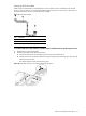
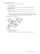
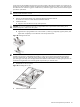
f. Fold the terminated end of the SCSI cable in the manner illustrated in the following figure.
g. Reattach the mylar sheet over the cable back to the air duct surface.
h. Route the SCSI cable through the cable management opening of the chassis’ partition wall.
Figure 24 SCSI cable routing for low-profile controller boards phase 3
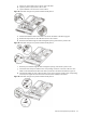
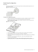
i. Route the power cable through the cable management opening of the chassis’ partition wall.
j. Connect the SCSI and power cables to their corresponding connectors on the rear of the new drive.
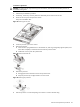
Make sure the terminated end of the SCSI cable is positioned in the manner illustrated in Figure 25.
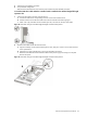
k. Check that all cables are clear of the hard drive carrier and are properly routed to their corresponding
connectors, then tighten the screw that secures the hard drive assembly to the chassis.
Figure 25 SCSI cable routing for low-profile controller boards phase 4