
ProLiant DL140 Generation 2 Server Maintenance and Service Guide

Removal and replacement procedures 21
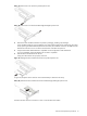
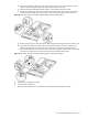
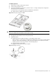
Figure 17 Removing the cover of the low-profile expansion slot
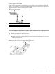
Figure 18 Removing the cover of the standard height/full-length expansion slot
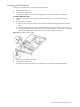
4. Remove the SCSI controller board from its protective packaging, handling it by the edges.
Some controller boards can only be installed in one slot but other boards can be configured to fit in either
slot by replacing the default bracket (attached to the board) with a different sized one. The different sized
bracket and instructions on how to attach it to the board is included in the option kit.
5. Verify that the board’s default bracket is compatible with the configuration of the selected slot.
If it is not compatible, replace the bracket with one that is compatible.
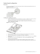
6. Slide the SCSI controller board into the slot.
Firmly press the board to seat it properly on the slot.
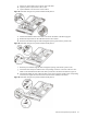
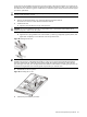
Figure 19 Installing the SCSI controller board in the low-profile expansion slot
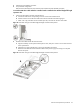
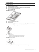
In Figure 20, the plane section of the PCI riser board assembly is dimmed out for clarity.
Figure 20 Installing the SCSI controller board in the standard height/full-length expansion slot
Proceed to the next section for instructions on how to route the SCSI drive cables.