
ProLiant DL140 Generation 2 Server Maintenance and Service Guide

Removal and replacement procedures 10
Removal and replacement procedures
Review the specifications of a new component before installing it to make sure it is compatible with the server.
When you integrate new components into the system, record its model and serial number, and any other
pertinent information for future reference. After completing any removal or replacement procedure, run the
diagnostics program to verify that all components operate properly.
Hardware configuration tools
In performing any hardware configuration procedure you may need the following tools:
• T-15 Torx screwdriver
• Flat-blade screwdriver
The following references and software tools may also be used:
• HP ProLiant DL140 Generation 2 Server Support CD
• IPMI Event Log
• Diagnostics software
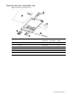
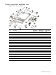
NOTE: The figures used in this guide to illustrate procedural steps are labeled numerically (i.e., 1, 2…). When
these figures are used in substep items, the alphabetically labeled instructions correspond to the numbered
labels on the related figure (i.e., Label 1 corresponds to step a, label 2 corresponds to step b, etc.). The
procedures described in this section assume that the server is out of the rack and is positioned on a flat, stable
surface.
Hardware configuration warnings
Read the following sections before performing any servicing or troubleshooting procedure.
WARNING! Only authorized technicians trained by HP should attempt to repair this equipment. Because of the
complexity of the individual boards and subassemblies, no one should attempt to make repairs at the
component level or to make modifications to any printed wiring board. Improper repairs can create a safety
hazard.
CAUTION: Whenever installing hardware or performing maintenance procedures requiring access to internal
components, it is recommended that all server data be backed up to avoid loss.
Symbols on equipment
These symbols may be located on equipment in areas where hazardous conditions may exist.
WARNING! This symbol, in conjunction with any of the following symbols, indicates the presence of a
potential hazard. The potential for injury exists if warnings are not observed. Consult your documentation for
specific details.
This symbol indicates the presence of hazardous energy circuits or electric shock hazards. Refer all servicing to
qualified personnel.
WARNING! To reduce the risk of injury from electric shock hazards, do not open this enclosure. Refer all
maintenance, upgrades, and servicing to qualified personnel.