
ProLiant DL140 Generation 2 Server Installation Sheet
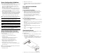
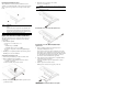


PCI Riser Board Expansion Slots
The two PCI-X riser boards att
ached to the PCI riser board
assembly convert the functionality of the system board expansion
slots to a pair of slots positioned at a 90°
angle from the system
board.
Item Component
1 Standard height/full-lengt
h 64-bit/133 MHz PCI-X riser
board
Users have the option to replace this riser board with a PCI
Express model using the PCI Express riser board option kit.
This will allow support for PCI Express x8 expansion boards.
2 Low profile 64-bit/133
MHz PCI-X riser board
Expansion Board Installation Guidelines
The system supports up to two
expansion boards at a time. Use
only HP supported expansion boards that meet the following
specifications:
• PCI or PCI-X compliant
— Connector: 32 or 64 bits wide, 3.3 V
— Speed
PCI board speed: 66 MHz
PCI-X board speed: 100 or 133 MHz
— Form factor: low profile or standard height/full-length
boards
• PCI Express x8 compliant (available only when the optional
PCI Express riser board is installed)
To install a PCI expansion board:
1.
Perform the pre-installation procedures described earlier.
2.
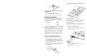
Remove the
PCI riser board assembly:
a.
Loosen the two captive thum
bscrews that secure the
assembly to the chassis.
b. Lift the assembly away from the chassis.
3. Identify the slot that is compatible with the expansion board
you intend to install.
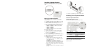
4.
Pull out the slot cover from the selected slot.
Store it for reassembly later.
CAUTION: Do not discard the slot cover. If the expansion board is
removed in the future, the slot cover must be reinstalled to
maintain proper cooling.
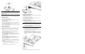
Removing the cover of the low–profile expansion slot
Removing the cover of the standard height/full-length
expansion slot
5. Remove the PCI expansion board from its protective
packaging, handling it by the edges.
Some expansion boards can only be installed in one slot but
other boards can be configured to fit in either slot by replacing
the default bracket (attached to the board) with a different sized
one. The different sized bracket
and instructions on how to
attach it to the board is in
cluded in the option kit.
6. Verify that the board’s default
bracket is compatible with the
configuration of the selected slot.
If it is not compatible, replace
the bracket with one that is
compatible.
7. Slide the expansion board into the slot.
Firmly press the board to seat it properly on the slot.
Installing the SCSI controller
board in the low–profile
expansion slot