
ProLiant DL140 Generation 2 Server Installation Sheet


Server Configuration Guidelines
Observe the following important guidelines before performing any
of the configuration steps listed in the next section.
• For safety information and detailed procedures related to step 3
of the “Server Configuration Overview” section, refer to
Chapter 2 of the
HP ProLiant DL140 Generation 2 Server
Maintenance and Service Guide.
• For safety information and detailed procedures related to the
rest of the steps listed in th
e “Server Configuration Overview”
section, refer to relevant chapter on the
HP ProLiant DL140
Generation 2 Server User Guide.
•
Refer to the HP ProLiant DL140 Generation 2 Server Support
CD
for additional information and updates not provided in this
installation sheet. You can al
so access additiona
l information
and documentation from the HP website at
http://www.hp.com/
,
either by connecting directly or through the
Support CD
.
NOTE: The procedures described in this installation sheet assume t
hat the
server is out of the rack and is positioned on a flat, stable surfa
ce.
IMPORTANT:
Observe the pre- and post-installation procedures described
in later sections when performing any configuration procedure.
CAUTION: Follow the ESD precautions listed in Chapter 2 of the
H
P
ProLiant DL140 Generation 2 Server Maintenance and Service
Guide
when handling any hardware component.
WARNING: Failure to properly turn off the server before you
open the server or before you start removing/installing hardware
components may cause serious damage as well as bodily harm.
WARNING: To reduce the risk of personal injury from hot
surfaces, allow the chassis and any installed hardware
component to cool before touching them.
Server Configuration Overview
The steps listed below give an overview of the necessary setup
procedures for preparing the HP ProLiant DL140 Generation 2
server for operation.
1. Select an appropriate site for the server.
2.
Unpack the server and rack-mounting hardware.
3.
Install other options.
Other options include additional memory, hard drives,
expansion boards, and external storage devices.
4. Connect the power cord an
d peripheral devices.
5. Turn on the server and dete
rmine the BIOS version.
Update the BIOS version if necessary.
6. Install a supported operating
system of your choice.
For detailed procedures, refer to the documentation provided
by the OS vendor.
NOTE: For a list of operating systems
supported by your ProLiant server,
go to
http://www.hp.com/go/supportos
.
7. Install the rack rails.
8. Mount the server in the rack.
9.
Configure the settings for the server’s management functions.
For detailed procedures, refer to the
Lights-Out 100i User
Guide.
Pre- and Post-Installation
Procedures
Pre-installation Procedures
1. Turn off the server and all the
peripherals connected to it.
2. Unplug all cables from the power
outlets to avoid exposure to
high energy levels that ma
y cause burns when parts are
short-circuited by metal objects such as tools or jewelry.
If necessary, label each one to expedite reassembly.
3. Disconnect telecommunication cab
les to avoid exposure to
shock hazard from ringing voltages.
4. Remove the top cover.
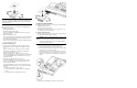
Post-installation Procedures
1. Be sure all components are installed according to the described
step-by-step instructions.
2. Check to make sure you have not left loose tools or parts inside
the server.
3. Reinstall any expansion board(s), peripheral(s), board cover(s),
and system cable(s) that have previously been removed.
4. Reinstall the top cover.
5. Connect all external cables an
d the AC power cord to the
system.
6. Press the power button
on the front panel to turn on the
server.
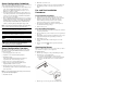
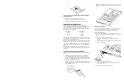
Opening the Server
The top cover is detachable. You need to remove this cover before
you can remove or replace a server component.
To open the server:
1. Perform steps 1 through 3 of the pre-installation procedures.
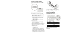
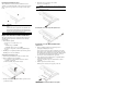
2. Detach the top cover
from the chassis:
a. Loosen the captive thumbscr
ew on the rear panel.
b. Slide the cover approximately 1.
25 cm (0.5 in) toward the
rear of the unit, then lift the cover to detach it from the
chassis.
3. Place the top cover in a safe place for reinstallation later.