
HP ProLiant DL120 G6 Server Installation Sheet
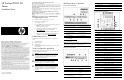

HP ProLiant DL120 G6
Server
Installation Sheet
Configuring the server
1. Connect the necessary peripherals to your server.
2. Determine the server BIOS version.
a. Power up the server.
b. Press the
Esc key at the HP logo screen, and then press the
Pause key to halt screen movement.
c. Note the server BIOS version.
d. Verify the server BIOS version against the latest BIOS
version listed for this server on the HP website:
http://www.hp.com.
e. If you do not have the latest BIOS, update the BIOS now.
f. Refer to your server’s
Maintenance and Service Guide
available on the HP website:
http://www.hp.com.
Default boot priority
By default, the server searches for boot devices in the following
order:
1. Removable devices
2. Optical disc drive
3. Hard disk drive
4. Embedded NIC, PXE (Preboot Execution Environment—remote
boot over LAN
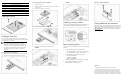
Server configuration guidelines
Read the following items before performing any of the installation
procedures described in later sections.
WARNING: Failure to properly turn off the system power
before you open the server or before you start removing
or installing hardware components may cause serious
damage as well as bodily harm.
WARNING: To reduce the risk of personal injury from
hot surfaces, allow the chassis and any installed
hardware component to cool before touching them.
CAUTION: Observe the ESD precautions, pre- and post-
installation procedures, and proper cabling management
described in Chapter 2 of your server’s
Maintenance
and Service Guide
when performing any installation
procedure.
Identifying server components
Front panel components
Item Component Item Component
1 Optical disc drive (ODD) 8 Hard disk drive (HDD) activity
LED
2 Serial label pull tab 9 Power/standby button/LED
3 USB ports 10 Hard disk drive 4
4 Unit identification (UID)
button/LED
11 Hard disk drive 3
5 Internal health LED 12 Hard disk drive 2
6 Embedded NIC 1
activity/link LED
7 Embedded NIC 2
activity/link LED
13 Hard disk drive 1
NOTE: In the above figure, the top section shows a system with hot-plug
hard drives, the bottom part shows a non-hot-plug model.
Rear panel components
Item Component Item Component
1 PSU cable socket 5 Embedded NIC 2
2 PS/2 keyboard port 6 Serial port
3 PS/2 mouse port 7 Low profile PCI expansion slot
cover
4 Embedded NIC 1/shared
management NIC port
8 Full-height/full-length expansion
slot cover
Item Component Item Component
9 T10/T15 wrench 12 Management NIC port
10 PCI cage screws 13 Video port
11 UID switch 14 USB ports
System board components
Item Code Component
1 PWRCN1 24-pin ATX system board power connector
2 DIMM6B Channel B 1
st
DDR3 memory slot
3 DIMM5D Channel B 2
nd
DDR3 memory slot
4 DIMM4F Channel B 3
rd
DDR3 memory slot
5 DIMM3A Channel A 1
st
DDR3 memory slot
6 DIMM2C Channel A 2
nd
DDR3 memory slot
7 DIMM1E Channel A 3
rd
DDR3 memory slot
8 FAN1 Processor fan 1 cable connector
9 FAN2 Processor fan 2 cable connector
10 FAN3 Processor fan 3 cable connector
11 CPU1 Processor
12 SATA5 ODD SATA cable connector
13 SATA4 HDD 4 SATA cable connector
14 SATA3 HDD 3 SATA cable connector
15 SATA2 HDD 2 SATA cable connector
16 CN7 HDD backplane SGPIO cable connector
17 SATA1 HDD 1 SATA cable connector
18 SATA6 Reserved
19 CN8 HDD backplane I2C cable connector
20 FAN5 System fan 4 cable connector
21 CN13 Front panel board cable connector
22 FPUSBCONN1 Front USB port cable connector
23 CN11 External SAS HDD LED cable connector
24 SKT1 Internal USB connector for STD USB
25 SW4 System configuration switch
26 USBCONN1 Internal USB connector for tape device
27 JP5 BMC recovery jumper
Part number: 580642-002
March 2010 (Second edition)