
HP ProLiant BL685c G7 Server Blade Installation Instructions
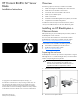

d. Remove the divider from the enclosure.
Installing interconnect modules
For specific steps to install interconnect modules, see the
documentation that ships with the interconnect module.
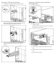
Interconnect bay numbering and device
mapping
• HP BladeSystem c7000 Enclosure
• HP BladeSystem c3000 Enclosure
To support network connections for specific signals, install an
interconnect module in the bay corresponding to the embedded NIC
or mezzanine signals.
Server
blade signal
c7000
interconnect
bay
c3000
interconnect
bay
Interconnect
bay labels
NIC 1
(Embedded)
1 1
NIC 2
(Embedded)
2 1
NIC 3
(Embedded)
1 1
NIC 4
(Embedded)
2 1
Mezzanine
1
3 and 4 2
Mezzanine
2
5 and 6* 3 and 4
7 and 8** 3 and 4
Mezzanine
3
5 and 6** 3 and 4
7 and 8* 3 and 4
* Dual port mezzanine card ports and four-port mezzanine card
ports 1 and 2
** Four-port mezzanine card ports 3 and 4
For detailed port mapping information, see the HP BladeSystem
enclosure installation poster or the HP BladeSystem enclosure setup
and installation guide on the HP website
(http://www.hp.com/go/bladesystem/documentation).
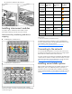
Connecting to the network
To connect the HP BladeSystem to a network, each enclosure must
be configured with network interconnect devices to manage signals
between the server blades and the external network.
Two types of interconnect modules are available for HP BladeSystem
c-Class enclosures: Pass-thru modules and switch modules. For more
information about interconnect module options, see the HP website
(http://www.hp.com/go/bladesystem/interconnects
).
Installing server blade options
Before installing and initializing the server blade, install any server
blade options, such as an additional processor, hard drive, or
mezzanine card. For server blade options installation information,
see the HP ProLiant BL685c G7 Server Blade User Guide on the HP
website (http://www.hp.com/go/bladesystem/documentation
).