
HP ProLiant BL660c Gen8 Server Blade Maintenance and Service Guide


Removal and replacement procedures 49
16.
Install all DIMM baffles ("DIMM baffles" on page 27).
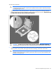
17. Install and route the cables for all capacitor packs. For more information on routing the cables, see
"FBWC capacitor pack cabling (on page 64)."
18. Install the hard drives ("Drive" on page 25).
19. Install the hard drive blanks ("Drive blank" on page 25).
20. Install the access panel ("Access panel" on page 24).
21. Install the server blade.
After you replace the system board, you must re-enter the server blade serial number and the product ID.
1. During the server blade startup sequence, press the F9 key to access RBSU.
2. Select the Advanced Options menu.
3. Select Service Options.
4. Select Serial Number. The following warnings appear:
WARNING! WARNING! WARNING! The serial number is loaded into the system during
the manufacturing process and should NOT be modified. This option should only
be used by qualified service personnel. This value should always match the
serial number sticker located on the chassis.
Warning: The serial number should ONLY be modified by qualified personnel.
This value should always match the serial number located on the chassis.
5. Press the Enter key to clear the warning.
6. Enter the serial number and press the Enter key.
7. Select Product ID. The following warning appears:
Warning: The Product ID should ONLY be modified by qualified personnel. This
value should always match the Product ID on the chassis.
8. Enter the product ID and press the Enter key.
9. Press the Esc key to close the menu.
10. Press the Esc key to exit RBSU.
11. Press the F10 key to confirm exiting RBSU. The server blade automatically reboots.
Server blade release lever assembly
To remove the component:
1. Power down the server blade (on page 22).
2. Remove the server blade (on page 23).
3. Remove the access panel ("Access panel" on page 24).
4. Remove all hard drives ("Drive" on page 25).
5. Remove all hard drive blanks ("Drive blank" on page 25).
6. Disconnect the capacitor pack cabling, if connected ("FBWC capacitor pack cabling" on page 64).
7. If installed, remove the FBWC capacitor pack.
8. Remove all DIMM baffles ("DIMM baffles" on page 27).
9. Remove all DIMMs ("DIMMs" on page 29).
10. Disconnect all cables from the drive backplane. For more information, see "Cabling (on page 64)."
11. Remove the front panel/drive cage assembly ("Front panel/drive cage assembly" on page 37).