
HP ProLiant BL620c G7 Server Blade Maintenance and Service Guide
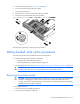
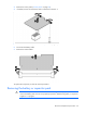
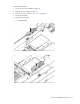
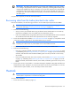
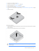
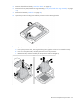
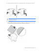
Table Of Contents
- HP ProLiant BL620c G7 Server Blade Maintenance and Service Guide
- Abstract
- Notice
- Contents
- Customer self repair
- Illustrated parts catalog
- Removal and replacement procedures
- Required tools
- Safety considerations
- Server blade preparation
- Access panel
- Hard drive blank
- Hard drive
- Mezzanine connector cover
- Left DIMM baffle
- Right DIMM baffle
- DIMM
- Heatsink blank
- Mezzanine card
- Front panel/hard drive cage assembly
- Battery-backed write cache procedures
- Heatsink
- Processor
- System board
- System battery
- Server blade release lever
- Release button
- HP Trusted Platform Module
- Diagnostic tools
- Server component identification
- Cabling
- Specifications
- Acronyms and abbreviations
- Index
Removal and replacement procedures 36
IMPORTANT: The battery pack might have a low charge when installed. In this case, a POST
error message is displayed when the server blade is powered up, indicating that the battery pack
is temporarily disabled. No action is necessary on your part. The internal circuitry automatically
recharges the batteries and enables the battery pack. This process might take up to four hours.
During this time, the cache module functions properly, but without the performance advantage of
the battery pack.
To replace the component, reverse the removal procedure.
Recovering data from the battery-backed write cache
If the server blade fails, use the following procedure to recover data temporarily stored in the BBWC.
CAUTION: Before starting this procedure, read the information about protecting against
electrostatic discharge ("Preventing electrostatic discharge" on page 22).
1. Perform one of the following:
o Set up a recovery server blade station using an identical server blade model. Do not install any
internal drives or BBWC in this server blade. (HP recommends this option.)
o Find a server blade that has enough empty drive bays to accommodate all the drives from the failed
server blade and that meets all the other requirements for drive and array migration.
2. Power down the failed server blade ("Power down the server blade" on page 23). If any data is stored
in the cache module, a green LED on the module flashes every 2 seconds.
CAUTION: Do not detach the cable that connects the battery pack to the cache module.
Detaching the cable causes any unsaved data in the cache module to be lost.
3. Transfer the hard drives from the failed server blade to the recovery server blade station.
4. Perform one of the following:
o If the array controller has failed, remove the cache module ("Removing the cache module" on page
33) and battery pack ("Removing the battery or capacitor pack" on page 34) from the failed array
controller, and install the cache module and battery pack on an array controller in the recovery
server blade.
o If the server blade has failed, remove the controller, cache module ("Removing the cache module"
on page 33), and battery pack ("Removing the battery or capacitor pack" on page 34) from the
failed server blade, and install the controller, cache module, and battery pack in the recovery server
blade.
5. Power up the recovery server blade. A 1759 POST message is displayed, stating that valid data was
flushed from the cache. This data is now stored on the drives in the recovery server blade. You can now
transfer the drives (and controller, if one was used) to another server blade.
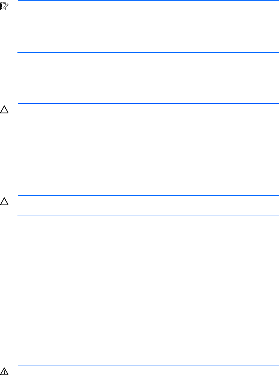
Heatsink
WARNING: To reduce the risk of personal injury from hot surfaces, allow the drives and the
internal system components to cool before touching them.
To remove the component:
1. Power down the server blade (on page 23).