HP ProLiant BL465c Gen8 Server Blade Maintenance and Service Guide Abstract This guide describes identification and maintenance procedures, diagnostic tools, specifications and requirements for hardware components and software. This guide is for an experienced service technician. HP assumes you are qualified in the servicing of computer equipment, trained in recognizing hazards in products, and are familiar with weight and stability precautions.
© Copyright 2012 Hewlett-Packard Development Company, L.P. The information contained herein is subject to change without notice. The only warranties for HP products and services are set forth in the express warranty statements accompanying such products and services. Nothing herein should be construed as constituting an additional warranty. HP shall not be liable for technical or editorial errors or omissions contained herein. Microsoft® and Windows® are U.S. registered trademarks of Microsoft Corporation.
Contents Customer self repair ...................................................................................................................... 5 Parts only warranty service ......................................................................................................................... 5 Illustrated parts catalog ............................................................................................................... 15 Server blade components ...........................................
Integrated Management Log ..................................................................................................................... 62 USB support ........................................................................................................................................... 62 Internal USB functionality ................................................................................................................ 63 External USB functionality ........................................
Customer self repair HP products are designed with many Customer Self Repair (CSR) parts to minimize repair time and allow for greater flexibility in performing defective parts replacement. If during the diagnosis period HP (or HP service providers or service partners) identifies that the repair can be accomplished by the use of a CSR part, HP will ship that part directly to you for replacement. There are two categories of CSR parts: • Mandatory—Parts for which customer self repair is mandatory.
Obligatoire - Pièces pour lesquelles la réparation par le client est obligatoire. Si vous demandez à HP de remplacer ces pièces, les coûts de déplacement et main d'œuvre du service vous seront facturés. Facultatif - Pièces pour lesquelles la réparation par le client est facultative. Ces pièces sont également conçues pour permettre au client d'effectuer lui-même la réparation.
In base alla disponibilità e alla località geografica, le parti CSR vengono spedite con consegna entro il giorno lavorativo seguente. La consegna nel giorno stesso o entro quattro ore è offerta con un supplemento di costo solo in alcune zone. In caso di necessità si può richiedere l'assistenza telefonica di un addetto del centro di supporto tecnico HP. Nel materiale fornito con una parte di ricambio CSR, HP specifica se il cliente deve restituire dei componenti.
defekte Teil nicht zurückschicken, kann HP Ihnen das Ersatzteil in Rechnung stellen. Im Falle von Customer Self Repair kommt HP für alle Kosten für die Lieferung und Rücksendung auf und bestimmt den Kurier-/Frachtdienst. Weitere Informationen über das HP Customer Self Repair Programm erhalten Sie von Ihrem Servicepartner vor Ort. Informationen über das CSR-Programm in Nordamerika finden Sie auf der HP Website unter (http://www.hp.com/go/selfrepair).
enviara el componente defectuoso requerido, HP podrá cobrarle por el de sustitución. En el caso de todas sustituciones que lleve a cabo el cliente, HP se hará cargo de todos los gastos de envío y devolución de componentes y escogerá la empresa de transporte que se utilice para dicho servicio. Para obtener más información acerca del programa de Reparaciones del propio cliente de HP, póngase en contacto con su proveedor de servicios local.
Neem contact op met een Service Partner voor meer informatie over het Customer Self Repair programma van HP. Informatie over Service Partners vindt u op de HP website (http://www.hp.com/go/selfrepair). Garantieservice "Parts Only" Het is mogelijk dat de HP garantie alleen de garantieservice "Parts Only" omvat. Volgens de bepalingen van de Parts Only garantieservice zal HP kosteloos vervangende onderdelen ter beschikking stellen.
No caso desse serviço, a substituição de peças CSR é obrigatória. Se desejar que a HP substitua essas peças, serão cobradas as despesas de transporte e mão-de-obra do serviço.
Customer self repair 12
Customer self repair 13
Customer self repair 14
Illustrated parts catalog Server blade components Item Description Spare part number Customer self repair (on page 5) Mechanical components 1 Access panel 686063-001 Mandatory1 2 Drive blank 670033-001 Mandatory1 3 Front panel/drive cage assembly 683820-001 Mandatory1 4 DIMM baffle 686062-001 Mandatory1 5 Heatsink blank 683819-001 Mandatory1 6 Mezzanine assembly 683822-001 Mandatory1 7 Hardware and plastics kit* 697743-001 Mandatory1 a) Enclosure connector cover — — Illustrated
Item Description Spare part number Customer self repair (on page 5) b) Mezzanine assembly retainer assembly — — c) Mezzanine assembly guide pins (2) — — d) T-15 system board screws (2) — — e) Serial label pull tab — — Processors — — a) 2.5-GHz, AMD Opteron Model 6380** 705217-001 Optional2 b) 2.4-GHz, AMD Opteron Model 6378* ** 705218-001 Optional2 c) 2.3-GHz, AMD Opteron Model 6376* ** 705219-001 Optional2 d) 1.8-GHz, AMD Opteron Model 6366 HE* ** 705225-001 Optional2 e) 2.
Item 11 Description Spare part number Customer self repair (on page 5) g) 600-GB, SAS, 10,000-rpm, 6G* 653957-001 Mandatory1 h) 900-GB, SAS, 10,000-rpm, 6G* 653971-001 Mandatory1 i) 1-TB, SAS, 7,200-rpm, 6G* 653954-001 Mandatory1 j) 500-GB, SATA, 7,200-rpm, 6G* 656107-001 Mandatory1 k) 1-TB, SATA, 7,200-rpm, 6G* 656108-001 Mandatory1 Solid state drives, SFF* — a) 200-GB, SAS, SLC, 6G 653961-001 Mandatory1 b) 200-GB, SAS, MLC, 6G 658580-001 Mandatory1 c) 400-GB, SAS, SLC, 6G 653962-001
Item Description Spare part number 16 Trusted Platform Module 505836-001 No3 17 FlexibleLOMs — a) HP Ethernet 10Gb 2-port 560FLB FlexibleLOM 656243-001 Mandatory1 b) HP Flex-10 10Gb 2-port 530FLB FlexibleLOM* 657132-001 Mandatory1 c) HP FlexFabric 10Gb 2-port 554FLB FlexibleLOM* 649940-001 Mandatory1 Ethernet Mezzanine* — a) HP Flex-10 10Gb 2-port 530M Adapter 657131-001 Mandatory1 b) HP Flex-10 10Gb 2-port 552M Adapter 675484-001 Mandatory1 c) HP FlexFabric 10Gb 2-port 554M Adapter 64
No: Non—Certaines pièces HP ne sont pas conçues pour permettre au client d'effectuer lui-même la réparation. Pour que la garantie puisse s'appliquer, HP exige que le remplacement de la pièce soit effectué par un Mainteneur Agréé. Ces pièces sont identifiées par la mention “Non” dans le Catalogue illustré. 3 Mandatory: Obbligatorie—Parti che devono essere necessariamente riparate dal cliente.
Illustrated parts catalog 20
Removal and replacement procedures Required tools You need the following items for some procedures: • T-15 Torx screwdriver (provided on the DIMM baffle) • T-10 Torx screwdriver (not provided with the server blade) • HP Insight Diagnostics software ("HP Insight Diagnostics" on page 61) Safety considerations Before performing service procedures, review all the safety information.
Symbols on equipment The following symbols may be placed on equipment to indicate the presence of potentially hazardous conditions. This symbol indicates the presence of hazardous energy circuits or electric shock hazards. Refer all servicing to qualified personnel. WARNING: To reduce the risk of injury from electric shock hazards, do not open this enclosure. Refer all maintenance, upgrades, and servicing to qualified personnel. This symbol indicates the presence of electric shock hazards.
This method initiates a controlled shutdown of applications and the OS before the server blade enters standby mode. • Press and hold the Power On/Standby button for more than 4 seconds to force the server blade to enter standby mode. This method forces the server blade to enter standby mode without properly exiting applications and the OS. If an application stops responding, you can use this method to force a shutdown. • Use a virtual power button selection through HP iLO.
3. Remove the server blade. 4. Place the server blade on a flat, level work surface. WARNING: To reduce the risk of personal injury from hot surfaces, allow the drives and the internal system components to cool before touching them. CAUTION: To prevent damage to electrical components, properly ground the server blade before beginning any installation procedure. Improper grounding can cause ESD. Access panel To remove the component: 1. Power down the server blade (on page 22). 2.
Drive blank Remove the component as indicated. To replace the component, squeeze the release latch and slide the drive blank into the bay until it clicks into place. Drive To remove the component: 1. Determine the status of the drive from the drive LED definitions (on page 71). 2. Back up all server blade data on the drive. 3. Remove the drive.
1. Prepare the drive. 2. Install the drive. 3. Determine the status of the drive from the drive LED definitions (on page 71). Enclosure connector cover To remove the component: 1. Place the server blade on a flat, level work surface. 2. Remove the enclosure connector cover.
To replace the component, reverse the removal procedure. DIMM baffle To remove the component: 1. Power down the server blade (on page 22). 2. Remove the server blade (on page 23). 3. Remove the access panel ("Access panel" on page 24). CAUTION: Always disconnect the drive cables from the SAS controller before removing the DIMM baffle. Failure to do so may result in damage to the SAS controller. 4. Disconnect the drive cables from the SAS controller. 5. Remove the DIMM baffle.
To replace the component: 1. Install the DIMM baffle. 2. Connect the drive cable connectors to the SAS controller. 3. Install the access panel ("Access panel" on page 24). DIMMs CAUTION: Use only HP DIMMs. DIMMs from other sources may adversely affect data integrity. To identify the DIMMs installed in the server blade, see "DIMM identification (on page 74)." To remove the component: 1. Power down the server blade (on page 22). 2. Remove the server blade (on page 23).
3. Remove the access panel ("Access panel" on page 24). CAUTION: Always disconnect the drive cables from the SAS controller before removing the DIMM baffle. Failure to do so may result in damage to the SAS controller. 4. Disconnect the drive cables from the SAS controller and remove the DIMM baffle ("DIMM baffle" on page 27). 5. Remove the DIMM. To replace the component, reverse the removal procedure. Mezzanine assembly To remove the component: 1. Power down the server blade (on page 22). 2.
4. Remove the mezzanine assembly from the server blade. To replace the component: 1. Align the mezzanine assembly with the guide pins on the system board, and then install the mezzanine assembly on the system board. 2. Press down firmly on the mezzanine assembly handles, and then close the mezzanine assembly latch. 3. Install the access panel ("Access panel" on page 24).
Mezzanine card To remove the component: 1. Power down the server blade (on page 22). 2. Remove the server blade (on page 23). 3. Remove the access panel ("Access panel" on page 24). 4. Remove the mezzanine assembly ("Mezzanine assembly" on page 29). 5. Remove the mezzanine card from the mezzanine assembly. To replace the component: 1. Align the mezzanine card with the guide pins on the mezzanine assembly.
2. Install the mezzanine card in the mezzanine assembly, and then tighten the mezzanine card screws to secure the card to the mezzanine assembly. 3. Align the mezzanine assembly with the guide pins on the system board, and then install the mezzanine assembly on the system board. 4. Press down firmly on the mezzanine assembly handles, and then close the mezzanine assembly latch. 5. Install the access panel ("Access panel" on page 24). FlexibleLOM To remove the component: 1.
2. Remove the server blade (on page 23). 3. Remove the access panel ("Access panel" on page 24). 4. Remove the mezzanine assembly ("Mezzanine assembly" on page 29). 5. Use the FlexibleLOM handle to remove the FlexibleLOM from the system board. To replace the component: 1. Align and install the FlexibleLOM. Press down on the handle to seat the FlexibleLOM on the system board. 2. Install the mezzanine assembly ("Mezzanine assembly" on page 29). 3.
SAS controller To remove the component: 1. Power down the server blade (on page 22). 2. Remove the server blade (on page 23). 3. Remove the access panel ("Access panel" on page 24). CAUTION: Always disconnect the drive cables from the SAS controller before removing the DIMM baffle. Failure to do so may result in damage to the SAS controller. 4. Disconnect the drive cables from the SAS controller and remove the DIMM baffle ("DIMM baffle" on page 27). 5.
To replace the component: 1. Install the SAS controller. 2. Install the DIMM baffle and connect the drive cable to the SAS controller ("DIMM baffle" on page 27). 3. Install the access panel ("Access panel" on page 24). NAND flash module for the Smart Array P220i Controller To remove the component: 1. Power down the server blade (on page 22). 2. Remove the server blade (on page 23). 3. Remove the access panel ("Access panel" on page 24).
6. Remove the NAND flash module from the Smart Array P220i Controller. To replace the component, reverse the removal procedure. FBWC procedures Three types of procedures are provided for the FBWC option: • Removing the SAS controller capacitor pack (on page 36) • Removing the mezzanine option capacitor pack (on page 37) • Recovering data from the FBWC (on page 38) Removing the SAS controller capacitor pack To remove the component: 1. Power down the server blade (on page 22). 2.
6. Remove the capacitor pack. To replace the component, reverse the removal procedure. Removing the mezzanine option capacitor pack To remove the component: 1. Power down the server blade (on page 22). 2. Remove the server blade (on page 23). 3. Remove the access panel ("Access panel" on page 24). 4. Disconnect the drive cables from the SAS controller and remove the DIMM baffle ("DIMM baffle" on page 27). 5. Disconnect the capacitor pack cable from the mezzanine option.
6. Remove the capacitor pack. To replace the component, reverse the removal procedure. Recovering data from the FBWC If the server blade fails, use the following procedure to recover data temporarily stored in the FBWC. CAUTION: Before starting this procedure, read the information about protecting against electrostatic discharge ("Preventing electrostatic discharge" on page 21). 1. Set up a recovery server blade station using an identical server blade model.
4. Remove the NAND flash module ("NAND flash module for the Smart Array P220i Controller" on page 35) and capacitor pack ("Removing the SAS controller capacitor pack" on page 36) from the failed server blade, and install the NAND flash module and capacitor pack in the recovery server blade. 5. Power up the recovery server blade. If data was saved on the NAND flash module, then a 1792 POST message appears, stating that valid data was flushed from the cache.
7. Remove the front panel/drive cage assembly. To replace the component, reverse the removal procedure. Heatsink blank To remove the component: 1. Power down the server blade (on page 22). 2. Remove the server blade (on page 23). 3. Remove the access panel ("Access panel" on page 24). CAUTION: Always disconnect the drive cables from the SAS controller before removing the DIMM baffle. Failure to do so may result in damage to the SAS controller. 4.
7. Remove the heatsink blank. To replace the component, reverse the removal procedure. Serial label pull tab To remove the component: 1. Power down the server blade (on page 22). 2. Remove the server blade (on page 23). 3. Remove the access panel ("Access panel" on page 24). CAUTION: Always disconnect the drive cables from the SAS controller before removing the DIMM baffle. Failure to do so may result in damage to the SAS controller. 4.
7. Remove the serial label pull tab. 8. Retain the information located on the original serial label pull tab and move it to the replacement serial label pull tab. To replace the component, reverse the removal procedure. Heatsink WARNING: To reduce the risk of personal injury from hot surfaces, allow the drives and the internal system components to cool before touching them. To remove the component: 1. Power down the server blade (on page 22). 2. Remove the server blade (on page 23). 3.
7. Remove the heatsink. To replace the component: 1. Clean the old thermal grease from the processor with the alcohol swab. Allow the alcohol to evaporate before continuing. 2. Remove the thermal interface protective cover from the heatsink. CAUTION: To avoid damage to the system board, processor socket, and screws, do not overtighten the heatsink screws. Use the wrench supplied with the system to reduce the possibility of overtightening the screws.
3. Align and install the heatsink. Alternate tightening the screws until the heatsink is seated properly. 4. Install the DIMM baffle and connect the drive cable to the SAS controller ("DIMM baffle" on page 27). 5. Install the front panel/drive cage assembly ("Front panel/drive cage assembly" on page 39). 6. Install all drives ("Drive" on page 25). 7. Install the access panel ("Access panel" on page 24).
To remove the component: 1. Power down the server blade (on page 22). 2. Remove the server blade (on page 23). 3. Remove the access panel ("Access panel" on page 24). CAUTION: Always disconnect the drive cables from the SAS controller before removing the DIMM baffle. Failure to do so may result in damage to the SAS controller. 4. Disconnect the drive cables from the SAS controller and remove the DIMM baffle ("DIMM baffle" on page 27). 5. Remove all hard drives ("Drive" on page 25). 6.
CAUTION: To avoid damage to the processor, do not touch the bottom of the processor, especially the contact area. To replace the component: IMPORTANT: Be sure the processor remains inside the processor installation tool. 1. If the processor has separated from the installation tool, carefully re-insert the processor in the tool. Handle the processor by the edges only, and do not touch the bottom of the processor, especially the contact area. 2. The processor fits one way into the socket.
CAUTION: THE PINS ON THE SYSTEM BOARD ARE VERY FRAGILE AND EASILY DAMAGED. To avoid damage to the system board: • Never install or remove a processor without using the processor installation tool. • Do not touch the processor socket contacts. • Do not tilt or slide the processor when lowering the processor into the socket. 3. Press the tabs on the processor tool to release the processor, and then remove the processor tool. 4. Close the processor socket retaining bracket and the processor locking lever.
6. Apply all the grease to the top of the processor in the following pattern to ensure even distribution. 7. Align and install the heatsink. Alternate tightening the screws until the heatsink is seated properly. 8. Install the front panel/drive cage assembly ("Front panel/drive cage assembly" on page 39). 9. Install the DIMM baffle and connect the drive cable to the SAS controller ("DIMM baffle" on page 27). 10. Install all drives ("Drive" on page 25). 11.
WARNING: The computer contains an internal lithium manganese dioxide, a vanadium pentoxide, or an alkaline battery pack. A risk of fire and burns exists if the battery pack is not properly handled. To reduce the risk of personal injury: • • • • Do not attempt to recharge the battery. Do not expose the battery to temperatures higher than 60°C (140°F). Do not disassemble, crush, puncture, short external contacts, or dispose of in fire or water. Replace only with the spare designated for this product.
5. Remove all hard drives ("Drive" on page 25). CAUTION: Always disconnect the drive cables from the SAS controller before removing the DIMM baffle. Failure to do so may result in damage to the SAS controller. 6. Disconnect the drive cables from the SAS controller and remove the DIMM baffle ("DIMM baffle" on page 27). 7. Remove all DIMMs ("DIMMs" on page 28). 8. Disconnect the mezzanine option capacitor pack cable, if installed ("Capacitor pack cabling" on page 64). 9.
15. Using the processor tool, remove the processor from the system board. CAUTION: To avoid damage to the processor, do not touch the bottom of the processor, especially the contact area. 16. Install the processor socket protective cover in each processor socket. 17. Remove the serial label pull tab.
To replace the system board: 1. Install the serial label pull tab. 2. Remove the processor socket protective cover. 3. Install the processor socket cover onto the processor socket of the failed system board. IMPORTANT: Be sure the processor remains inside the processor installation tool.
4. If the processor has separated from the installation tool, carefully re-insert the processor in the tool. Handle the processor by the edges only, and do not touch the bottom of the processor, especially the contact area. 5. The processor fits one way into the socket. Use the alignment guides on the processor and socket to properly align the processor with the socket. Install the processor on the spare system board. THE PINS ON THE SYSTEM BOARD ARE VERY FRAGILE AND EASILY DAMAGED.
6. Press the tabs on the processor tool to release the processor, and then remove the processor tool. 7. Close the processor socket retaining bracket and the processor locking lever. CAUTION: Be sure to close the processor socket retaining bracket before closing the processor locking lever. The lever should close without resistance. Forcing the lever closed can damage the processor and socket, requiring system board replacement. 8.
10. Install the heatsink ("Heatsink" on page 42). IMPORTANT: Install all components with the same configuration that was used on the failed system board. 11. Install all components removed from the failed system board. 12. Install the front panel/hard drive cage assembly ("Front panel/drive cage assembly" on page 39). 13. Install all drives ("Drive" on page 25). IMPORTANT: To avoid damage to the server blade, support the riser board when installing the TPM board and rivet. 14.
11. Press the F10 key to confirm exiting RBSU. The server blade automatically reboots. Server blade release lever assembly To remove the component: 1. Power down the server blade (on page 22). 2. Remove the server blade (on page 23). 3. Remove the access panel ("Access panel" on page 24). 4. Remove all hard drives ("Drive" on page 25). CAUTION: Always disconnect the drive cables from the SAS controller before removing the DIMM baffle. Failure to do so may result in damage to the SAS controller. 5.
12. Slide the system board approximately 1.27 cm (0.50 inches) towards the rear of the server, and then lift the system board from the base pan. 13. Remove the three T-10 screws from the outside of the base pan, and then remove the server blade release lever bracket. 14. Remove the T-10 screw from the inside of the base pan and then remove the server blade release lever assembly. To replace the component: 1.
2. Install the server blade release lever bracket, and then install the T-10 screw from the inside of the base pan. 3. Align the system board, and then slide it into place inside the base pan.
4. While holding the system board in place, turn the base pan on the side and install the four screws on the bottom of the base pan. 5. Place the server blade on a flat, level work surface. IMPORTANT: Install all components in the same configuration prior to removing the system board. 6. Install the heatsink blank ("Heatsink blank" on page 40). 7. If a capacitor pack option is installed and cabled to a mezzanine option, install this capacitor pack and route the cable to the mezzanine option.
Diagnostic tools HP product QuickSpecs For more information about product features, specifications, options, configurations, and compatibility, see the product QuickSpecs on the HP Product Bulletin website (http://www.hp.com/go/productbulletin).
HP Insight Diagnostics HP Insight Diagnostics is a proactive server blade management tool, available in both offline and online versions, that provides diagnostics and troubleshooting capabilities to assist IT administrators who verify server blade installations, troubleshoot problems, and perform repair validation. HP Insight Diagnostics Offline Edition performs various in-depth system and component testing while the OS is not running.
• Memory capacity and speed • Firmware/BIOS HP Active Health System does not collect information about Active Health System users' operations, finances, customers, employees, partners, or data center, such as IP addresses, host names, user names, and passwords. HP Active Health System does not parse or change operating system data from third-party error event log activities, such as content created or passed through by the operating system.
Internal USB functionality An internal USB connector is available for use with security key devices and USB drive keys. This solution provides for use of a permanent USB key installed in the internal connector, avoiding issues of clearance on the front of the rack and physical access to secure data. External USB functionality HP provides external USB support to enable local connection of USB devices for server blade administration, configuration, and diagnostic procedures.
Cabling Cabling resources Cabling configurations and requirements vary depending on the product and installed options. For more information about product features, specifications, options, configurations, and compatibility, see the product QuickSpecs on the HP Product Bulletin website (http://www.hp.com/go/productbulletin).
Drive cabling Using the HP c-Class Blade SUV Cable The HP c-Class Blade SUV Cable enables the user to perform server blade administration, configuration, and diagnostic procedures by connecting video and USB devices directly to the server blade. For SUV cable connectors, see "HP c-Class Blade SUV Cable (on page 75).
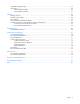
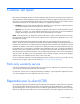
3. Connect a USB mouse to one USB connector. 4. Connect a USB keyboard to the second USB connector. Item Description 1 Monitor 2 USB mouse 3 USB keyboard 4 HP c-Class Blade SUV Cable Accessing local media devices Use the following configuration when configuring a server blade or loading software updates and patches from a USB CD/DVD-ROM. Use a USB hub when connecting a USB CD-ROM drive to the server blade. The USB hub provides additional connections. 1.
o USB mouse Item Description 1 Monitor 2 USB CD/DVD-ROM drive 3 USB keyboard 4 USB hub 5 USB mouse 6 HP c-Class Blade SUV Cable Cabling 67
Troubleshooting Troubleshooting resources The HP ProLiant Gen8 Troubleshooting Guide, Volume I: Troubleshooting provides procedures for resolving common problems and comprehensive courses of action for fault isolation and identification, issue resolution, and software maintenance on ProLiant servers and server blades. To view the guide, select a language: • English (http://www.hp.com/support/ProLiant_TSG_v1_en) • French (http://www.hp.com/support/ProLiant_TSG_v1_fr) • Spanish (http://www.hp.
Component identification Front panel components Item Description 1 Serial label pull tab 2 HP c-Class Blade SUV connector* (behind the serial label pull tab) 3 Drive bay 4 Server blade release lever 5 Server blade release button *The SUV connector and the HP c-Class Blade SUV Cable are used for some server blade configuration and diagnostic procedures.
Front panel LEDs and buttons Item Description Status 1 Health status LED bar Solid Green = Normal (System is powered on.) Flashing Green = Power On/Standby Button service is being initialized. Flashing Amber = Degraded condition Flashing Red = Critical condition Off = Normal (System is in standby.) 2 Power On/Standby Solid Green = System is powered on. button and System Flashing Green = System is waiting to power on; Power On/Standby button is power LED pressed.
Drive LED definitions Item LED Status Definition 1 Locate Solid blue The drive is being identified by a host application. Flashing blue The drive carrier firmware is being updated or requires an update. Rotating green Drive activity Off No drive activity Solid white Do not remove the drive. Removing the drive causes one or more of the logical drives to fail. Off Removing the drive does not cause a logical drive to fail. Solid green The drive is a member of one or more logical drives.
Item Description 1 Processor 2 DIMM slots 2 Processor 1 DIMM slots 3 Internal USB connector 4 Pass-thru board 5 TPM connector 6 Mezzanine connector 1 (Type A mezzanine only) 7 MicroSD card slot 8 Mezzanine connector 2 (Type A or type B mezzanine) 9 Enclosure connector 10 System maintenance switch 11 FlexibleLOM connectors (2) 12 Drive power cable connector 13 Processor socket 1 (populated) 14 Processor socket 2 15 System battery 16 HP c-Class Blade SUV cable connector The s
CAUTION: Clearing CMOS and/or NVRAM deletes configuration information. Be sure to properly configure the server or data loss could occur. Mezzanine connector definitions A PCIe x8 mezzanine connector supports x16 cards at up to x8 speeds. Item PCIe Mezzanine connector 1 x8, Type A mezzanine card only Mezzanine connector 2 x16, Type A or B mezzanine card DIMM slot locations DIMM slots are numbered sequentially (1 through 8) for each processor.
DIMM identification To determine DIMM characteristics, use the label attached to the DIMM and the following illustration and table. Item Description Definition 1 Size — 2 Rank 1R 2R 3R 4R 3 Data width x4 = 4-bit x8 = 8-bit 4 Voltage rating L = Low voltage (1.35V) U = Ultra low voltage (1.
Tool location A Torx T-15 screwdriver is located on the DIMM baffle.
Specifications Environmental specifications Specification Value — Temperature range* Operating 10°C to 35°C (50°F to 95°F) Non-operating -30°C to 60°C (-22°F to 140°F) Relative humidity (noncondensing)** — Operating 10% to 90% @ 28°C (82.4°F) Non-operating 5% to 95% @ 38.7°C (101.7°F) Altitude† — Operating 3050 m (10,000 ft) Non-operating 9144 m (30,000 ft) * The following temperature conditions and limitations apply: - All temperature ratings shown are for sea level.
Acronyms and abbreviations AMP Advanced Memory Protection FBWC flash-backed write cache iLO Integrated Lights-Out IML Integrated Management Log LRDIMM load reduced dual in-line memory module MLC multilevel cell POST Power-On Self Test RBSU ROM-Based Setup Utility RDIMM registered dual in-line memory module SAS serial attached SCSI SATA serial ATA SIM Systems Insight Manager Acronyms and abbreviations 77
SLC single-level cell UDIMM unregistered dual in-line memory module UID unit identification USB universal serial bus Acronyms and abbreviations 78
Documentation feedback HP is committed to providing documentation that meets your needs. To help us improve the documentation, send any errors, suggestions, or comments to Documentation Feedback (mailto:docsfeedback@hp.com). Include the document title and part number, version number, or the URL when submitting your feedback.
Index A access panel 15, 24 Active Health System 61 B batteries, replacing 48 battery 15, 48, 71 buttons 69 C cables 15, 64, 65 cabling 64, 65 cabling, drive 65 cabling, hard drive 65 capacitor pack 36, 37 cautions 21 components 15, 21, 31, 69 components, identification 15, 69 components, mechanical 15 components, system 15 connectors 69 controller 15, 34 CSR (customer self repair) 5 customer self repair (CSR) 5, 15 D data recovery 38 diagnosing problems 68 diagnostic tools 60, 61 diagnostics utility 61
heatsink blank 15, 40, 42 HP c-Class Blade SUV Cable 15, 65, 69, 75 HP Insight Diagnostics 21, 61 HP Insight Diagnostics survey functionality 61 I illustrated parts catalog 15 iLO (Integrated Lights-Out) 61, 62 IML (Integrated Management Log) 62 InfiniBand mezzanine 15 Insight Diagnostics 21, 61 Integrated Management Log (IML) 62 internal USB functionality 63 L LED, health 70 LED, power button 70 LED, system power 70 LEDs 71 LEDs, hard drive 71 LEDs, NIC 70 LEDs, SAS hard drive 71 LEDs, troubleshooting 68
T-15 Torx screwdriver 21, 75 tool locations 75 tools 21, 75 Torx screwdriver 21, 75 TPM (Trusted Platform Module) 59 troubleshooting 68 troubleshooting resources 68 troubleshooting, firmware upgrade utility 68 Trusted Platform Module (TPM) 15, 59 U USB connectors 75 USB devices 65 USB support 62 utilities 60 utilities, deployment 60 V video connector 75 video connector cabling 75 video devices 65 W warnings 21 Index 82