
HP ProLiant BladeSystem p-Class System Maintenance and Service Guide

Connectors, LEDs, and Switches 97
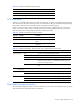
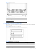
NOTE: The location of the power management module switches, connectors, and LEDs on 1U and 3U
enclosures is the same.
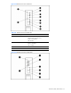
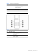
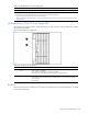
Use Figure 4-35 and Table 4-36 to identify LED locations and functions.
Figure 4-35 Power management module LEDs
Table 4-36 Power Management Module LEDs
Item LED Description Status
1 Management bus activity Amber = Activity *
Off = No activity
2 Management link Green = Link *
Off = No link
3 Power Green = Power available
Off = No power available
4 Fault Red = Fault condition
Off = No fault condition
5 Unit identification Blue = Unit identified
Off = Unit not identified
6/7 Power configuration Off/Green = Power zone 1 (default)
Green/Green = Power zone 2 (secondary)
* All management link connector LEDs flash on all management modules when
management modules are cabled improperly. Management link connector LEDs flash on the
power management module only when power configuration switches are set improperly.
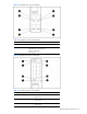
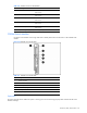
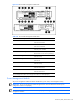
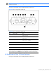
HP BladeSystem p-Class 1U Power Enclosure
Use Figure 4-36 and Table 4-37 to identify LED locations and functions.