
ProLiant BL40p Server Blade Maintenance and Service Guide

Connectors, LEDs, and Switches
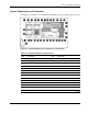
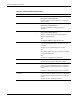
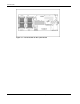
Table 4-2: System Components and Connectors continued
Item Component Item Component
14 Battery-Backed Write Cache Enabler 31 Processor fan connector
15 Ethernet passthrough board (connects
to chassis)
32 PPM slot 2
16 RJ-45 connectors 33 Processor socket 2
17 NIC I/O board 34 LED/power switch board with I/O
pass-through
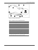
Diagnostic and Local I/O Cables
CAUTION: Disconnect the diagnostic cable or the Local I/O cable from the port when not in
use. The port and connector do not provide permanent connections.
CAUTION: Rear iLO connector performance degrades when the local I/O cable or the
diagnostic cable is installed, even when the iLO connector on the cable is not in use.
CAUTION: Always match the local I/O cable labeled with the I/O icon to the I/O port also
labeled with the I/O icon. The diagnostic cable and port have no labels. Mismatched cables
prevent proper connection.
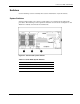
Use either the diagnostic cable or the local I/O cable to perform some server blade
configuration and diagnostic procedures. Depending on the model, the server blade will have
either a diagnostic port or an I/O port. The I/O port only accepts the local I/O cable and the
diagnostic port only accepts the diagnostic cable. If the server blade has an I/O icon next to
the port on the front of the server blade, use the local I/O cable. If the port has no icon, use
the diagnostic cable.
Refer to Figure 4-4 and Table 4-3 to identify the I/O icon and the diagnostic and local I/O
cable connectors.
4-4 HP ProLiant BL40p Server Blade Maintenance and Service Guide