
ProLiant BL40p Server Blade Maintenance and Service Guide

Connectors, LEDs, and Switches
System Components and Connectors
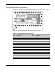
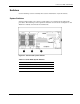
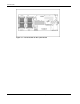
Use Figure 4-3 and Table 4-2 to identify ProLiant BL40p system components and connectors.
Figure 4-3: ProLiant BL40p system components and connectors
Table 4-2: System Components and Connectors
Item Component Item Component
1 Processor socket 3 18 Smart Array 5i Plus memory module
2 LED/power switch board connector 19 I/O Pass-through connector
3 PPM slot 3 20 System board
4 SCSI I2C cable connector 21 DC power converter connector
5 PPM slot 4 22 DIMM slots (6)
6 Processor socket 4 23 System board power modules (2)*
7 System battery 24 Channel B SCSI connector
8 SCSI fan power connector 25 System maintenance switch (SW3)
9 PCI-X mezzanine board connector 26 Channel A SCSI connector
10 PCI-X mezzanine board 27 Processor 1
11 64-bit/100 MHz PCI-X slot 2 28 SCSI power connector
12 64-bit/100 MHz PCI-X slot 1 29 PPM 1
13 PCI-X mezzanine power module* 30 System ID switch (SW1)
*same component
continued
HP ProLiant BL40p Server Blade Maintenance and Service Guide 4-3