
ProLiant BL35p Server Blade Maintenance and Service Guide
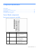
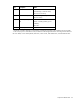
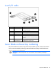
Table Of Contents
- HP ProLiant BL35p Server Blade Maintenance and Service Guide
- Notice
- Contents
- Illustrated parts catalog
- Removal and replacement procedures
- Safety considerations
- Preparation procedures
- ATA drive cage assembly
- ATA hard drive option
- SAS drive cage assembly
- SAS hard drive option
- SAS controller and cables
- Air baffle (dual-core processor models only)
- DIMMs
- Processor
- Fan assembly
- Dual Port Fibre Channel Adapter (2 GB)
- NIC riser board
- Power converter module
- Power button/LED cable
- Server blade handle
- System board assembly
- Server blade blanks
- HP BladeSystem p-Class sleeve
- HP BladeSystem p-Class sleeve board
- Diagnostic tools
- Component identification
- Specifications
- Acronyms and abbreviations
- Index
Component identification 38
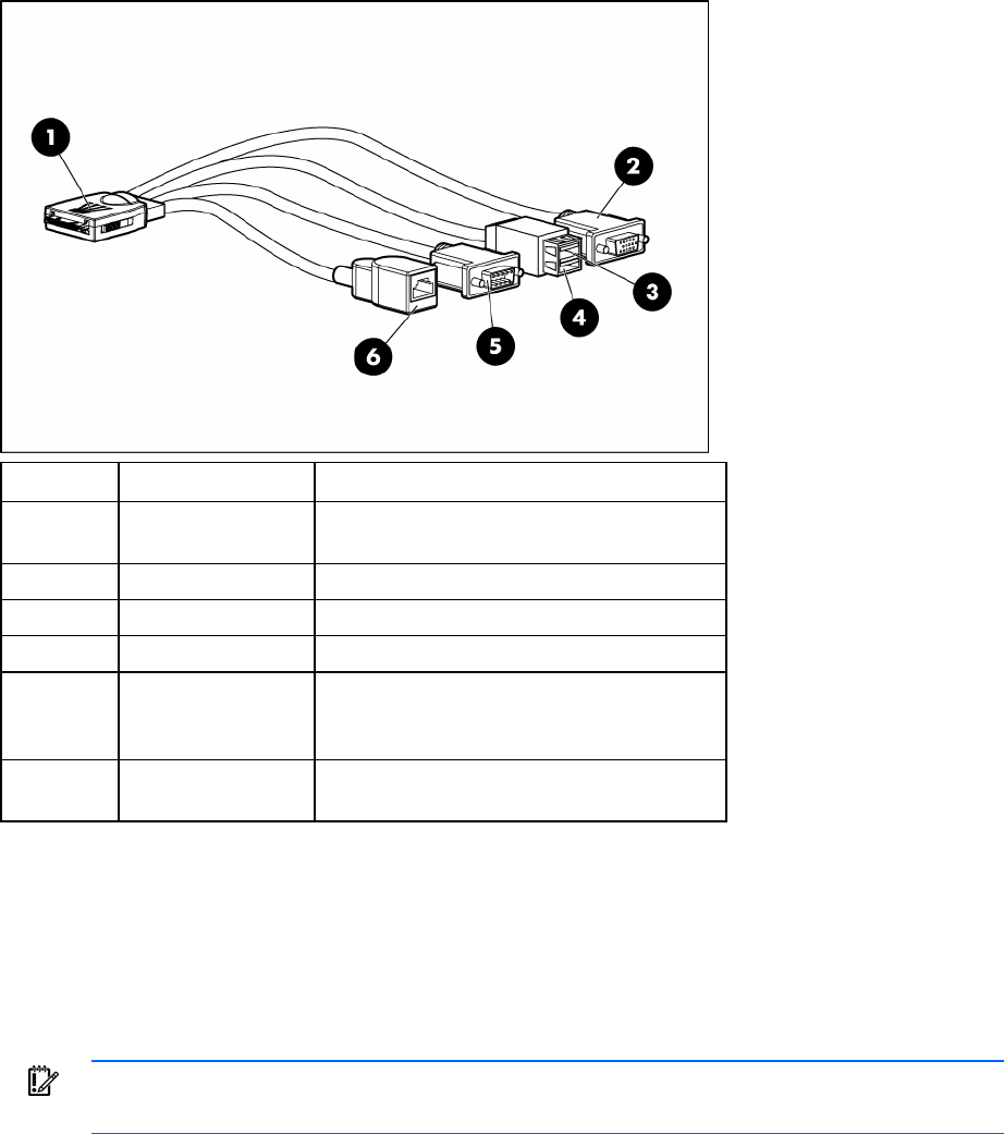
Local I/O cable
Item Connector Description
1 Local I/O For connecting to the local I/O port on the
server blade front panel
2 Video For connecting a video monitor
3 USB 1 For connecting a USB device
4 USB 2 For connecting a USB device
5 Serial For trained personnel to connect a null-modem
serial cable and perform advanced diagnostic
procedures
6 iLO RJ-45
(10/100 Ethernet)
For connecting an Ethernet to the server blade
iLO interface from a client device
Server blade enclosure bay numbering
Each server blade enclosure requires a pair of interconnect modules to provide network access for data
transfer. Interconnect modules reside in the far right and far left bays of the server blade enclosure. Be
sure to review server blade bay numbering to determine the HP ProLiant BL35p Server Blade external
network connections on the interconnects.
IMPORTANT: When looking at the rear of the enclosure, server blade bay numbering is
reversed.