
ProLiant BL35p Server Blade Maintenance and Service Guide
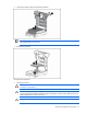
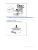
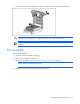
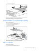
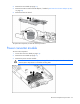
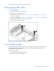
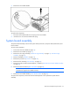
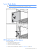
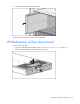
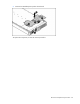
Table Of Contents
- HP ProLiant BL35p Server Blade Maintenance and Service Guide
- Notice
- Contents
- Illustrated parts catalog
- Removal and replacement procedures
- Safety considerations
- Preparation procedures
- ATA drive cage assembly
- ATA hard drive option
- SAS drive cage assembly
- SAS hard drive option
- SAS controller and cables
- Air baffle (dual-core processor models only)
- DIMMs
- Processor
- Fan assembly
- Dual Port Fibre Channel Adapter (2 GB)
- NIC riser board
- Power converter module
- Power button/LED cable
- Server blade handle
- System board assembly
- Server blade blanks
- HP BladeSystem p-Class sleeve
- HP BladeSystem p-Class sleeve board
- Diagnostic tools
- Component identification
- Specifications
- Acronyms and abbreviations
- Index
Removal and replacement procedures 27
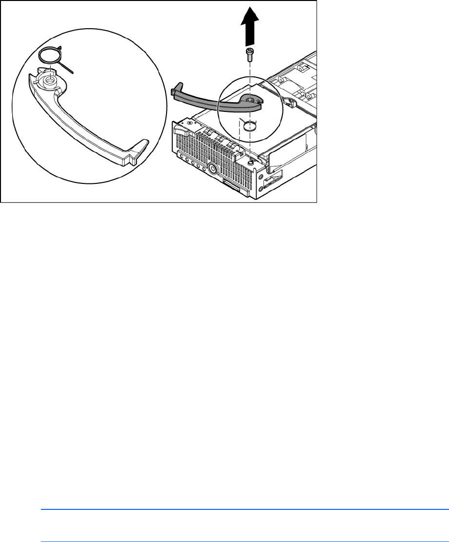
3.
Remove the server blade handle.
To replace the component:
1. Place the server blade handle over the spring on the server blade.
2. Install the screw to secure the handle and spring.
System board assembly
The system board assembly consists of the system board, the chassis, the power button/LED board, and
the two cables.
To remove the component:
1. Power down the server blade (on page 13).
2. Remove the server blade (on page 13).
3. Remove the drive cage assembly ("ATA drive cage assembly" on page 14, "SAS drive cage
assembly" on page 15).
4. Remove all DIMMs ("DIMMs" on page 19).
5. Remove the processors ("Processor" on page 20).
6. Remove the fan assembly ("Fan assembly" on page 23).
7. Remove the Dual Port Fibre Channel Adapter, if installed ("Dual Port Fibre Channel Adapter (2 GB)"
on page 24).
8. Remove the NIC riser board ("NIC riser board" on page 24).
NOTE: Always retain the server blade handle. The handle contains a serial number that
maintains the original server blade warranty.
9. Remove the server blade handle ("Server blade handle" on page 26).
To replace the component, reinstall all removed subcomponents in the replacement system board
assembly.