
HP ProIiant BL2x220c G6 Server Blade Maintenance and Serivce Guide

Removal and replacement procedures 25
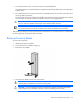
Install the server B assembly
For access component identification, see "Access components (on page 60)."
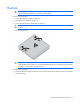
1. Engage the front edge of the server B assembly with the front edge of the server A assembly.
CAUTION: To avoid possible damage to mezzanine card cables, route any cables so that they do
not become pinched when the server B assembly is installed.
IMPORTANT:
To avoid possible damage to the serial label pull tab, extend the serial label pull
tab approximately 1 cm (0.4 in) before installing the server B assembly on the server A assembly.
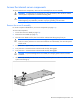
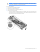
2. Lower the server B assembly onto the server A assembly.
3. Align the signal and power connectors on the server B assembly with the corresponding connectors on
the server A assembly.
CAUTION: The jackscrews control the unseating and seating of critical system connectors.
Failure to use the jackscrews to remove and install the server B assembly can cause the system
boards to fail.
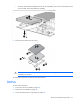
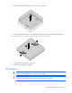
4. Engage the threads on jackscrew 1 and tighten six turns clockwise.
5. Engage the threads on jackscrew 2 and tighten fully.
6. Tighten jackscrew 1 fully.
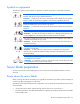
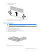
Install the server blade
CAUTION:
To prevent improper cooling and thermal damage, do not operate the server blade
enclosure unless all bays are populated with either a component or a blank.
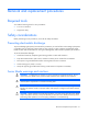
Install the component as indicated:
Hard drive